Hill hold for a vehicle

a technology for a clutch and a vehicle, which is applied in the direction of vehicle sub-unit features, braking systems, transportation and packaging, etc., can solve the problems of increasing wear and damage of the clutch, causing heat build-up in the clutch, and avoiding potential excessive wear or damage of the clutch

Active Publication Date: 2007-01-23
FORD GLOBAL TECH LLC
View PDF10 Cites 19 Cited by
  • Summary
  • Abstract
  • Description
  • Claims
  • Application Information

AI Technical Summary

Benefits of technology

[0009]An advantage of an embodiment of the present invention is that an automated manual transmission may operate in a hill hold situation while avoiding potential excessive wear or damage to the clutch.
[0010]Another advantage of an embodiment of the present invention is that the method can be performed without requiring the addition of transmission hardware to accomplish the hill hold function.
[0011]A further advantage of an embodiment of the present invention is that the hill hold function may be performed without creating potential concern to the vehicle operator. The protection of the clutch during a hill hold situation is accomplished without generating warning alerts to the vehicle operator or causing the vehicle to pulsate.

Problems solved by technology

One significant concern with these new systems, however, is the potential for heat build-up in the clutch while the vehicle is in a hill hold mode (i.e., the transmission is in a forward gear and the vehicle operator uses the accelerator pedal to maintain the vehicle at a stand still on a hill).
But for an automated type transmission with a clutch instead of a torque converter, the clutch will create the slippage, which creates heat build-up in the clutch.
This heat build-up can occur relatively quickly, and can approach temperatures that may cause significantly increased wear and possibly damage the clutch.
But the vehicle operator may ignore the warnings.
Others have suggested the addition of one-way clutches or other transmission hardware to accomplish a hill hold function, but these types of solutions add to the cost and complexity of the transmission.
However, such pulsation being felt throughout the vehicle may cause concern for both the vehicle operator and other occupants.
But this method may also cause a concern for the vehicle operator or vehicle occupants.

Method used


Image

  • Hill hold for a vehicle
  • Hill hold for a vehicle
  • Hill hold for a vehicle

Examples


Embodiment Construction

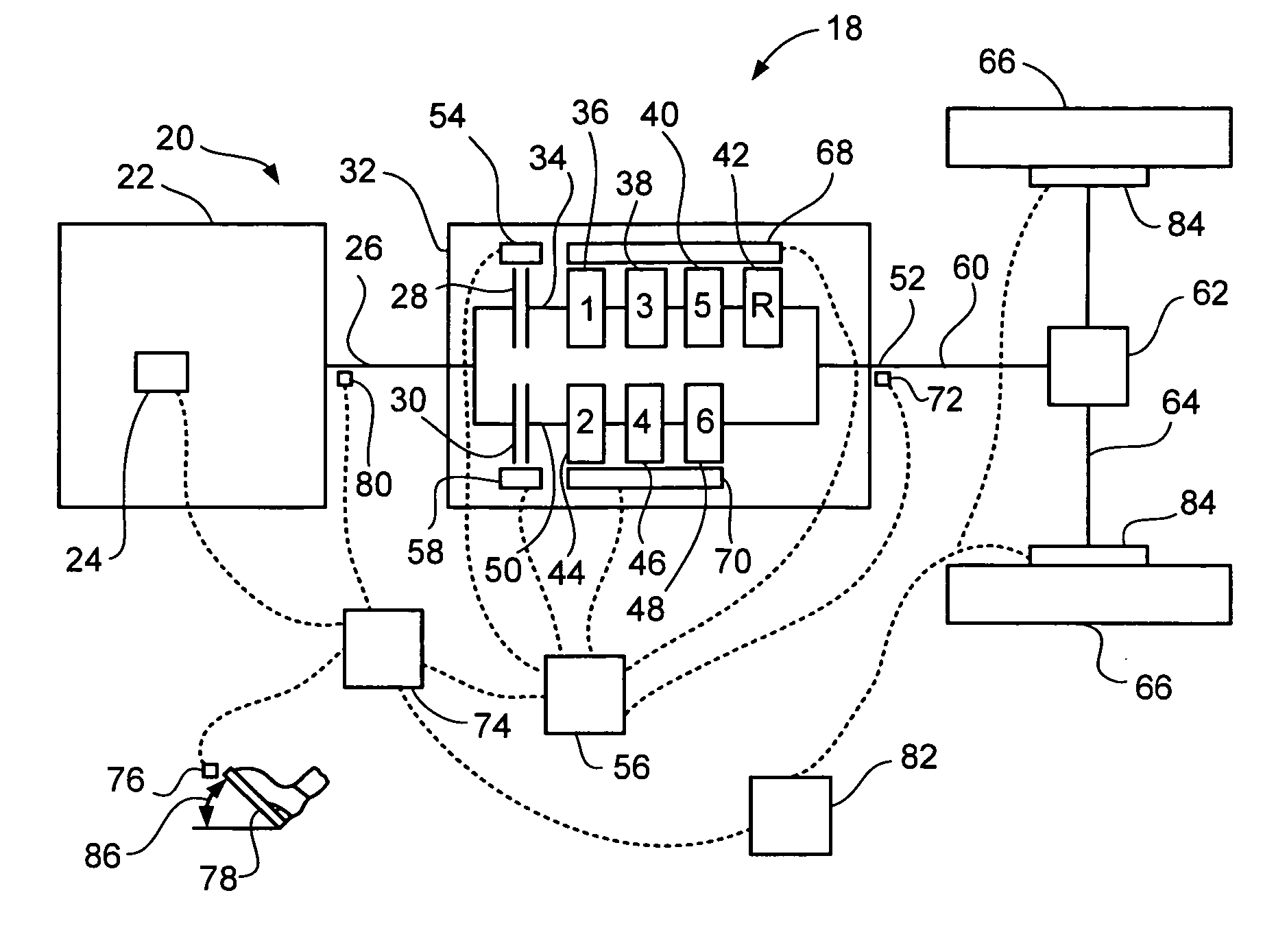
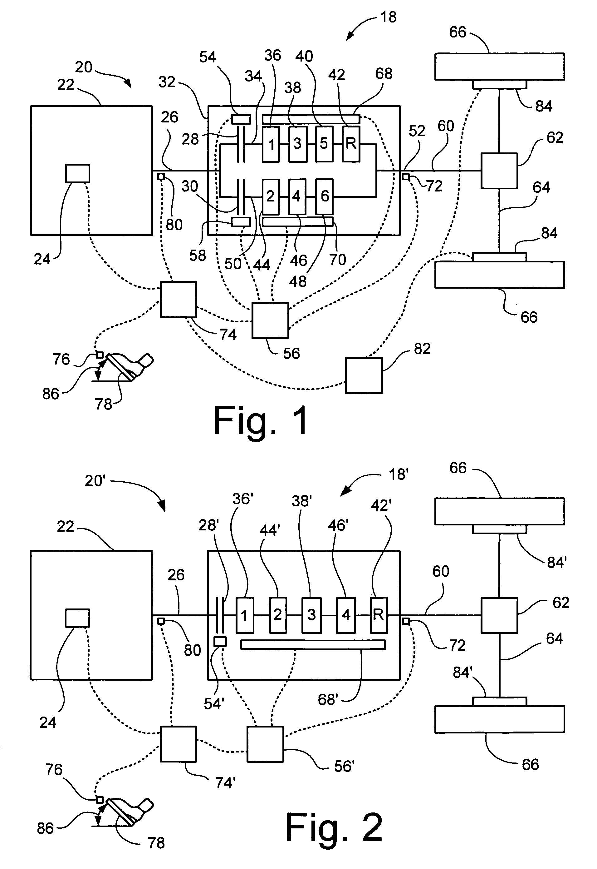
[0017]FIG. 1 illustrates a portion of a vehicle 18, having a vehicle powertrain 20 that includes an engine 22, with an electronically controlled throttle 24 and an engine output shaft 26. The engine 22 may be a conventional gasoline or diesel engine, or some other type of engine if so desired. The output shaft 26 splits in two and is coupled to a first clutch 28 and a second clutch 30. The first and second clutches 28, 30 are preferably dry clutches but may also be wet clutches instead, and may be located within a transmission 32 or adjacent to the transmission 32. The transmission includes a transmission output shaft 52 that connects to the rest of the powertrain 20, which may include a drive shaft 60, differential 62, axle 64, and wheels / tires 66. While the configuration appears generally as a rear wheel drive arrangement, the present invention is equally applicable to a front wheel drive arrangement as well.

[0018]The transmission 32 is preferably a type that has gear sets similar...


PUM


Abstract

A vehicle hill hold may be accomplished, for a vehicle having an automated clutch between the engine output and the transmission input, while protecting the clutch from potential excess wear due to overheating. A hill hold may be accomplished by automatically switching the torque holding the vehicle in place from the clutch to the brakes. Alternatively, a hill hold may be accomplished by increasing an accelerator pedal position sensitivity and switching the clutch between fully engaged and fully disengaged based on changes in the pedal position.

Description

BACKGROUND OF THE INVENTION [0001]The present invention relates to clutches employed with vehicle transmissions, and more particularly to preventing overheating of such clutches.[0002]Dry clutches connected between the engine output and the transmission input are conventionally employed with vehicles having manual transmissions. The engagement of these clutches are controlled by a vehicle operator pressing on or releasing a clutch pedal. While these conventional manual transmissions have some drawbacks relative to conventional automatic transmissions—the need for the vehicle operator to actuate the clutch pedal and manually shift gears—they are still employed due to some inherent advantages. Namely, a conventional clutch and manual transmission is typically less expensive than a conventional automatic transmission and torque converter, and the conventional manual transmission arrangement does not have the energy losses associated with the torque converter.[0003]Consequently, attempt...

Claims


Application Information

Patent Timeline
Patent Type & Authority Patents(United States)
IPC IPC(8): B60T11/10
CPCB60W10/02B60W30/18118F16D48/06B60W10/184Y10T477/745B60W2510/0291B60Y2400/428F16D2500/10412F16D2500/1045F16D2500/30404F16D2500/3144F16D2500/3166F16D2500/50224F16D2500/50296F16D2500/50841Y10T477/6389Y10T477/75
Inventor JLANG, HONGCOWAN, RON
Owner FORD GLOBAL TECH LLC
Why Eureka
Try Eureka