Adjustable bone prostheses and related methods

a bone prosthesis and mounting assembly technology, applied in the direction of prosthesis, shoulder joints, couplings, etc., can solve the problems of corresponding loss of mobility and function, limited adjustment range of conventional mounts, and inability to hold the desired position of conventional mounts

Inactive Publication Date: 2007-01-23
TORNIER INC
View PDF42 Cites 62 Cited by
  • Summary
  • Abstract
  • Description
  • Claims
  • Application Information

AI Technical Summary

Problems solved by technology

Injury or disease to the joint often results in destruction or deterioration of the head of the humerus, leading to pain and a corresponding loss of mobility and function.
However, conventional mounts provide only a limited range of adjustment, typically allowing only two degrees of freedom, i.e., linearly along an X-axis and Y-axis.
Further, even upon locking the device in a desired position, conventional mounts may not hold the desired position.

Method used


Image

  • Adjustable bone prostheses and related methods
  • Adjustable bone prostheses and related methods
  • Adjustable bone prostheses and related methods

Examples


embodiment # 2

[0181]B. Embodiment #2:

[0182]Disk Slide Mechanism

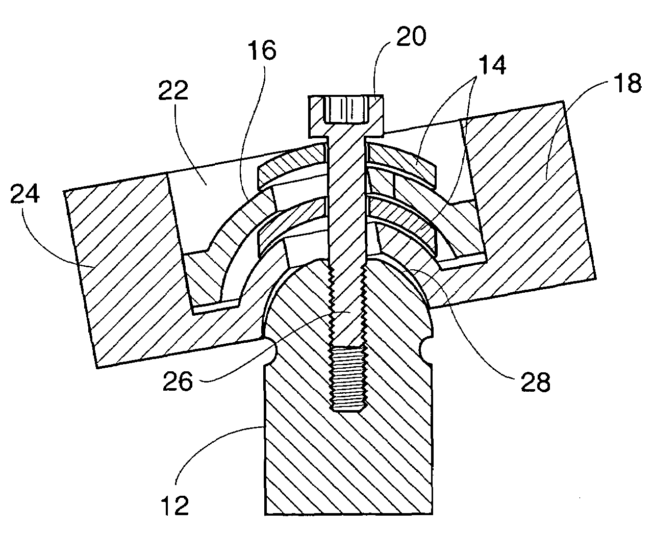
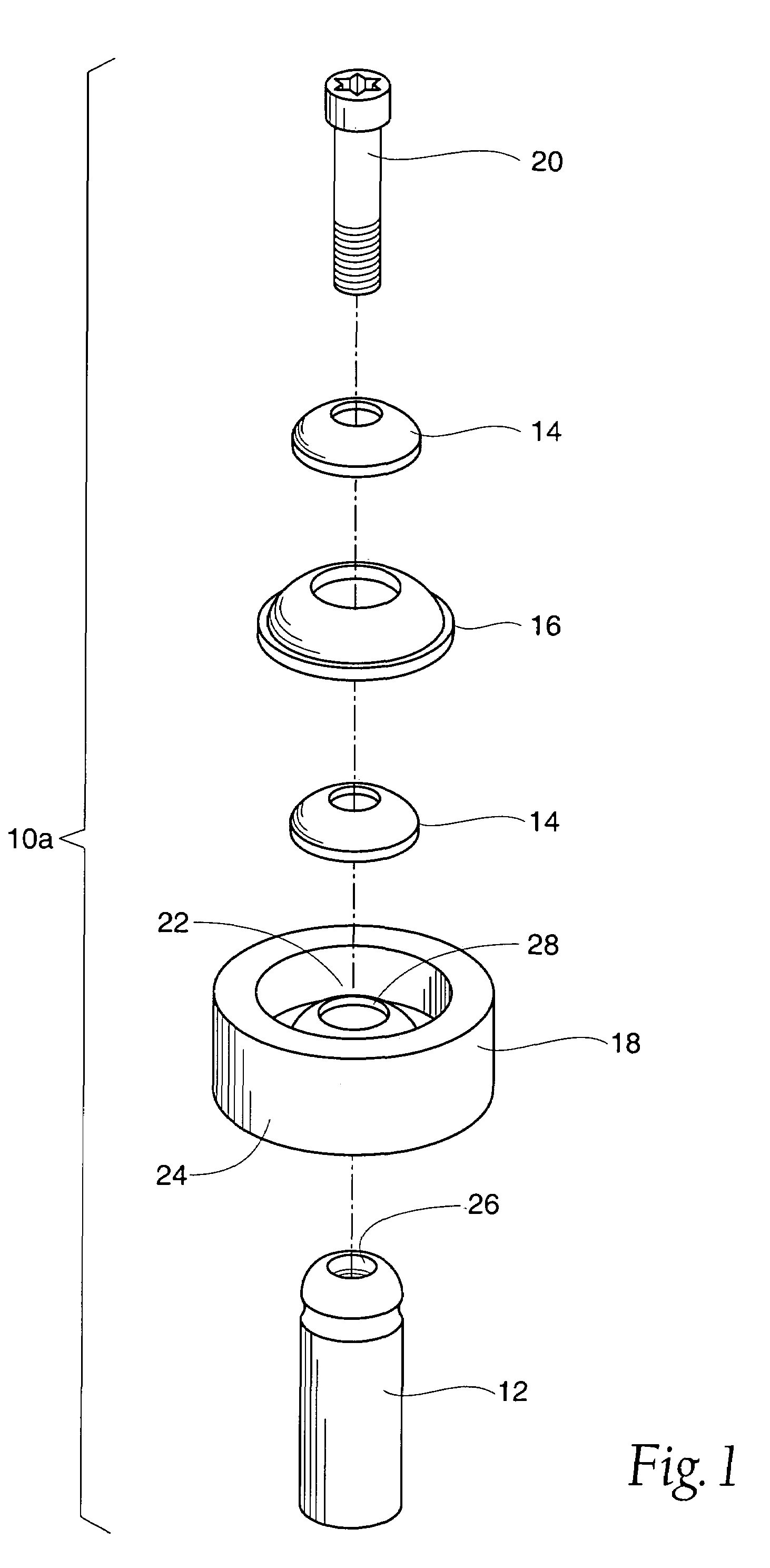
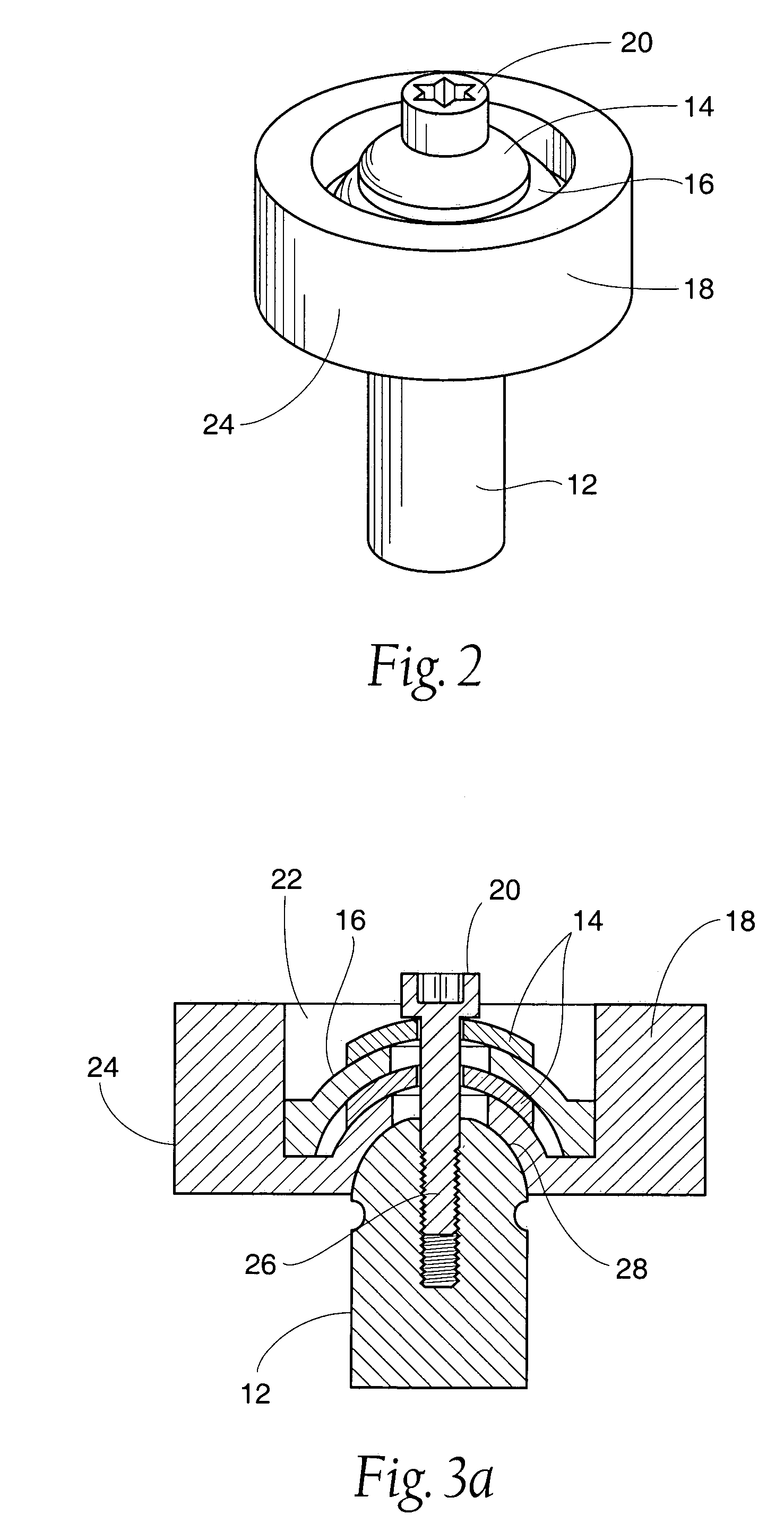
[0183]FIGS. 30a–34 detail another embodiment of a shoulder prosthesis mounting system 10D embodying features of the invention. With reference to FIGS. 30a and 30b, the system 10D comprises a stem 46, a pivot pin 12, a mounting ring 140, a bottom disk 142, a top disk 144, an artificial head 42, and a locking tool 146.

[0184]The stem is a conventional stem 46 and serves to receive a pivot pin 12, as previously described for system 10C The pivot pin 12 is similar in configuration to the pivot pin of System 10C. The post 120 is adapted to pass through the bottom disk 142 and the mounting ring 140 to mate with the stem 46, e.g., by threaded engagement.

[0185]As FIG. 31 shows, the ball 118 is sized to rest within the bottom disk 142. This arrangement allows the ball 118 to serve as a pivot surface, thereby permitting adjustment of the mounting ring 140.

[0186]As best seen in FIG. 30a, the mounting ring 140 is comprised of an outer ring 148 hav...


PUM


Abstract

Adjustable prostheses and related methods provide a wide range of adjustment along or about multiple axes. The prostheses and related methods make possible a straightforward, yet robust way of securing, e.g., a humeral head prosthesis in a desired position and maintaining the prosthesis in the desired position during use.

Description

RELATED APPLICATIONS[0001]This application is a divisional of co-pending U.S. application Ser. No. 10 / 041,722, filed on 8 Jan. 2002, which claims the benefit of provisional Application Ser. No. 60 / 271,895, filed on 27 Feb. 2001, entitled “Adjustable Head Prosthesis for the Shoulder.”FIELD OF THE INVENTION[0002]This invention generally relates to an adjustable mounting assembly and alignment system for a bone prosthesis and related methods.BACKGROUND OF THE INVENTION[0003]A shoulder joint consists of a ball-and-socket type coupling of the humerus to the scapula. The humerus forms the ball, and the socket is formed at the glenoid cavity of the scapula. Injury or disease to the joint often results in destruction or deterioration of the head of the humerus, leading to pain and a corresponding loss of mobility and function. In such cases, it is often necessary to provide a replacement joint surface, i.e., a prosthesis, for the head of the humerus that mates with the glenoid cavity.[0004]...

Claims


Application Information

Patent Timeline
Patent Type & Authority Patents(United States)
IPC IPC(8): A61F2/40A61F2/00A61F2/02A61F2/30A61F2/46F16C11/06F16C11/10F16M11/14
CPCA61F2/4684F16C11/0661F16C11/106F16M11/14A61F2/4014A61F2/40Y10T403/32622A61F2002/30332A61F2002/30378A61F2002/30405A61F2002/30433A61F2002/30434A61F2002/30507A61F2002/30514A61F2002/30538A61F2002/30553A61F2002/30611A61F2002/30617A61F2002/30797A61F2002/30884A61F2002/30899A61F2002/4037A61F2002/4044A61F2002/4062A61F2002/4638A61F2002/4681A61F2220/0025A61F2220/0033A61F2220/0041A61F2250/0006A61F2250/0008A61F2250/0063A61F2250/0097A61F2310/00017Y10T403/32606Y10T403/32639A61F2002/30604
Inventor CALLAWAY, GEORGE HADLEYMCDEVITT, DENNIS M
Owner TORNIER INC
Why Eureka
Try Eureka