Grinding jig set and grinding method

a technology of grinding jigs and jig sets, which is applied in the direction of workpiece holders, manufacturing tools, lapping machines, etc., can solve the problems of reducing product quality, affecting product quality, and affecting product quality,

Inactive Publication Date: 2007-01-30
NGK INSULATORS LTD
View PDF11 Cites 2 Cited by
  • Summary
  • Abstract
  • Description
  • Claims
  • Application Information

AI Technical Summary

Benefits of technology

[0026](19) The method according to (18), wherein, when an adhesive is previously applied to the surface of the grinding jig and the objects to be ground are secured to that surface by positioning them so that the objects penetrate the adhesive to the extent that one half or more of their length is embedded in the adhesive, a press operation is carried out by causing an elastic material with specific hardness to be present on the surface of the adhesive to reduce the embedding height of the objects to be ground in the adhesive.
[0031]According to the present invention, a grinding jig set comprising a combination of several jig units and a method for grinding a number of objects such as ceramic electronic parts are provided. The method comprises a series of steps from arranging the objects to be ground on a grinding jig (a master plate) through removing the ground objects from the grinding jig after completion of grinding process, smoothly and precisely without damaging a number of the objects to be ground and without altering the arrangement pattern of the objects to be ground from the start through the end of the series of steps.

Problems solved by technology

However, when a number of objects to be ground, particularly those having a small mechanically weak beam-like projections, such as a great number of small electronic parts made from ceramics, are arranged on the allocation tray by a manual operation, the objects may be damaged during an operation such as picking-up or handling with hard tools such as tweezers.
In addition, when an object to be ground has a complicated shape (such as a U-shape) which may easily become entangled with other objects of the same type, these objects may be damaged by entanglement or rubbing against each other.
Furthermore, when the objects to be ground adhering to an adhesive tape are transferred onto the grinding jig, the objects may crack or be broken during the operation of the removing from the adhesive tape, thereby decreasing the product quality.
In addition, manually locating a number of the objects to be ground onto an allocation tray while maintaining the arrangement pattern and transferring them onto an adhesive tape are extremely time-consuming, inefficient, and complicated operations.

Method used


Image

  • Grinding jig set and grinding method
  • Grinding jig set and grinding method
  • Grinding jig set and grinding method

Examples


example 1

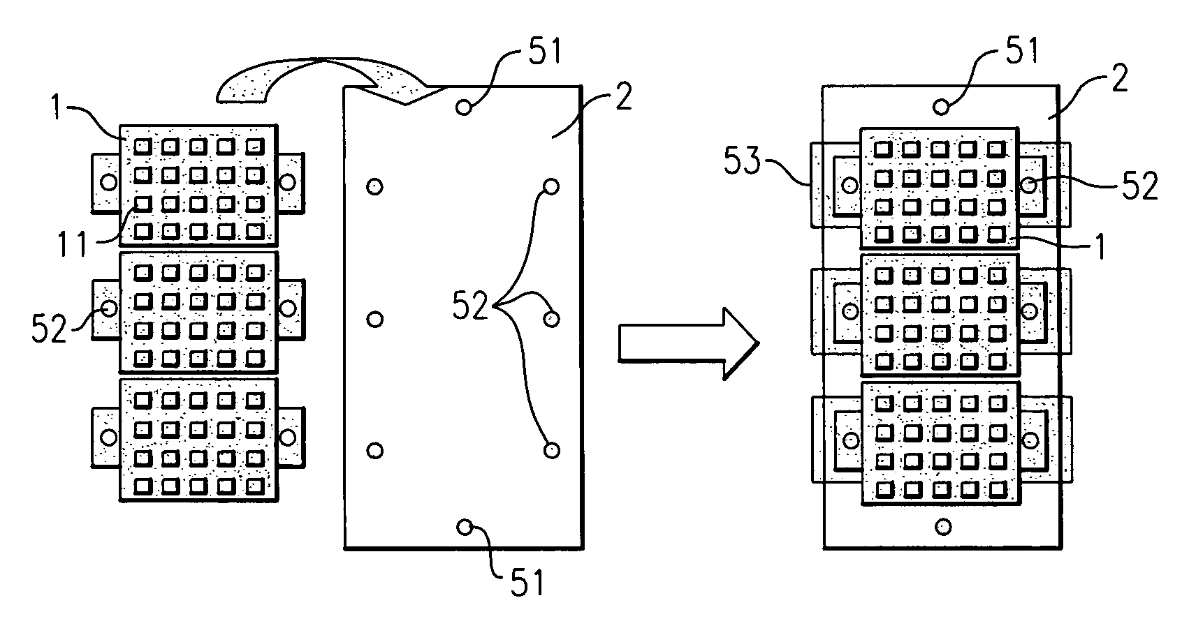
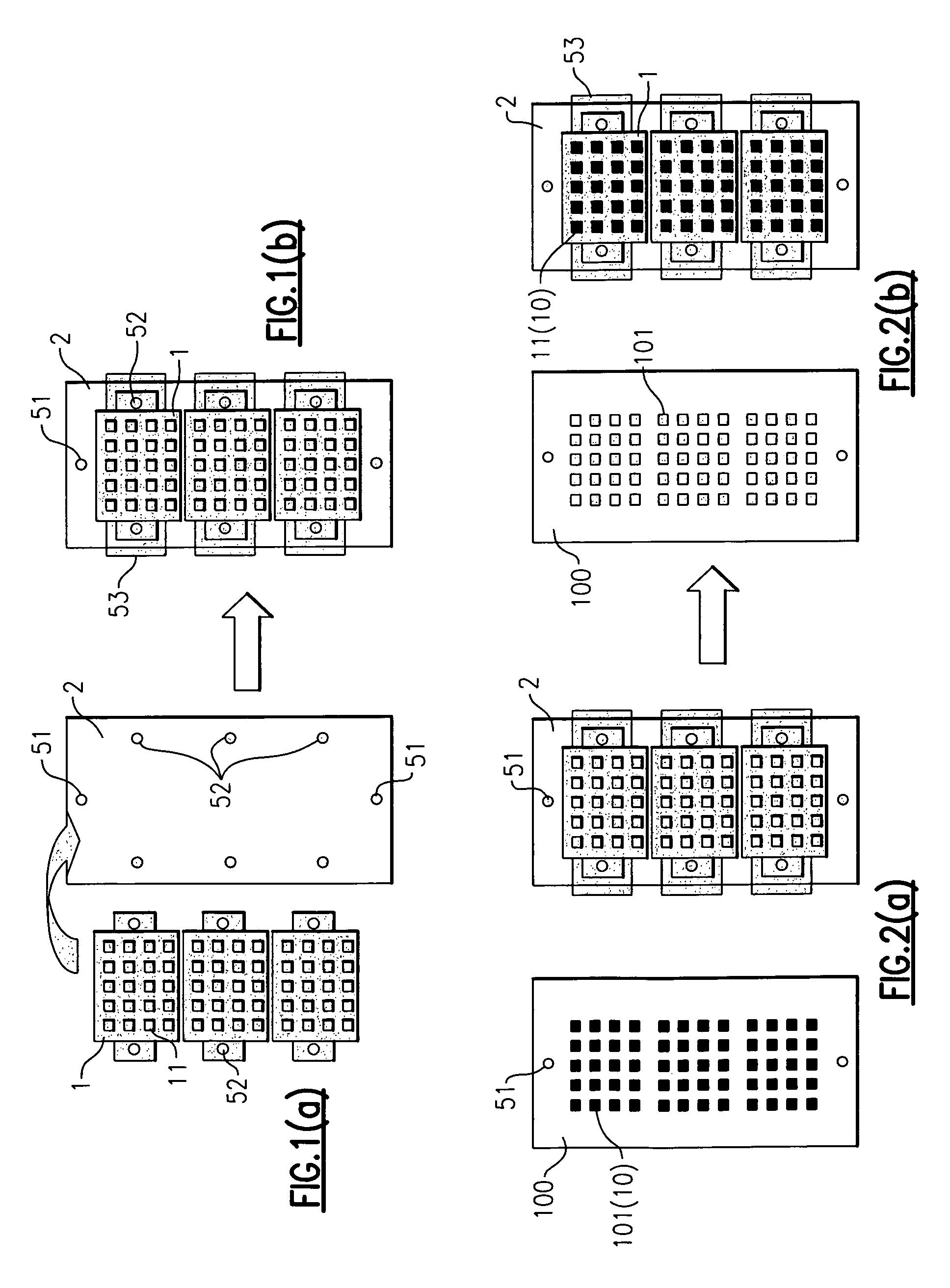
[0081]Laminates of ceramics (zirconia, PZT) and metals (gold, platinum) were used as objects to be ground. Each objects to be ground had two U-shaped beam-like projections which may be broken by a small external force. The objects to be ground which were placed in a starting tray beforehand were moved to small allocation trays, transferred to a dividing plate, and then to a grinding jig (a master plate). As the elastic body used for pressing, a silicone rubber sheet with a hardness of 50 and a thickness of 3 mm was used. The embedding length of the adhesive (“Shift Wax” manufactured by Nikka Seiko Co., Ltd.) to the grinding jig was reduced by elastic deformation of 20 μm or more. A grinding allowance of 10 to 15 μm was provided and only the objects to be ground were allowed to come in contact with the plate during grinding. Contact of the adhesive with the plate and process solution was prevented, thereby avoiding a decrease in grinding efficiency due to lack of a grinding fluid or ...

example 2

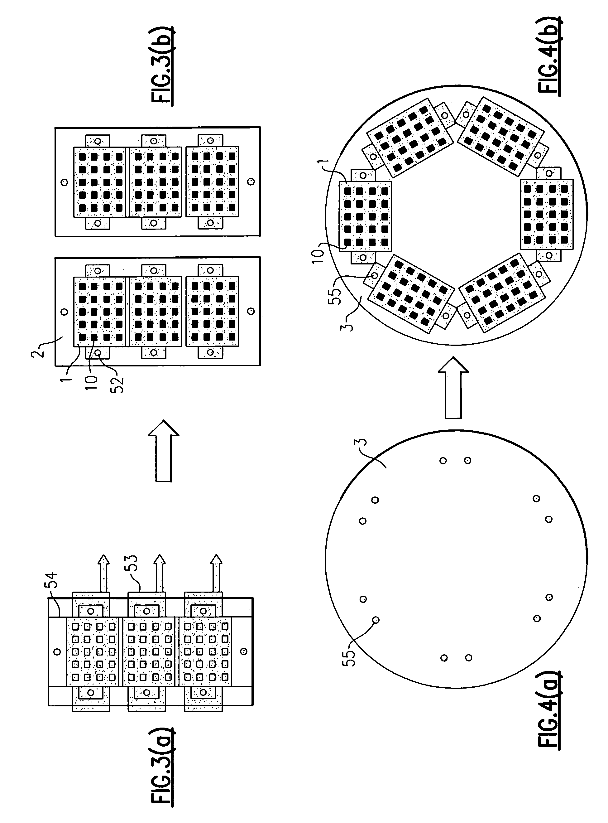
[0082]The experiment was carried out in the same manner as in Example 1, except that a spot spacer was installed on the master plate. A spot spacer with an external diameter of 3 mm and a thickness 25 μm greater than the thickness of the objects to be ground was used. To avoid an excess load on the plate at an early stage, a spot spacer of which the surface coming in contact with the plate was chamfered was used. Installation of the spot spacer prevented production of scratches because a brush was not used to remove foreign matter from the objects to be ground, and also precluded damage to the objects to be ground by a brush.

[0083]Experiments of Examples 1 and 2 confirmed that removal of 3 μm or more per 10 minutes can be achieved without reducing the process performance and without producing scratches and chipping.

[0084]The grinding jig set and the method of grinding of the present invention can be effectively used particularly in the field of manufacturing ceramic electronic parts...


PUM


Abstract

A grinding jig set comprising a combination of several jig units and a method for grinding a number of objects are provided. The method comprises a series of steps from arranging the objects to be ground on a grinding jig (a master plate) through removing the ground objects from the grinding jig after completion of grinding process, smoothly and precisely without damaging a number of the objects to be ground and without altering the arrangement pattern of the objects to be ground from the start through the end of the series of steps. The jig set for grinding comprises a set of jig units used for a series of processing from allocation of objects to be ground on a grinding jig through removing the ground objects from the grinding jig after the grinding operation. The jig units include a small allocation tray, a dividing tray which can transfer the objects to be ground retained in the small allocation tray from a starting tray to the small allocation tray, a dividing plate which can arrange the objects to be ground laid on the small allocation tray onto the surface of a grinding jig in the transferred state, and a removing tray onto which the ground objects removed from the surface of the grinding jig by a specified removing process can be relocated in the transferred state and divided into partial patterns.

Description

BACKGROUND OF THE INVENTION[0001]1. Field of the Invention[0002]The present invention relates to a grinding jig set and a method for grinding a number of objects. More particularly, the present invention relates to a grinding jig set comprising a combination of several jig units and a method for grinding a number of objects such as ceramic electronic parts, the method comprising a series of steps from arranging the objects to be ground on a grinding jig (a master plate) through removing the ground objects from the grinding jig after completion of grinding process, smoothly and precisely without damaging a number of the objects to be ground and without altering the arrangement pattern of these objects from the start through the end of the series of steps.[0003]2. Background Art[0004]A special process is required for grinding (lapping, for example) a number of objects (such as ceramic electronic parts, for example) not only to prevent variations and damage in the objects to be ground ...

Claims


Application Information

Patent Timeline
Patent Type & Authority Patents(United States)
IPC IPC(8): B24B49/00B24B37/04B24B41/06
CPCB24B7/162Y10S451/914Y10S269/90
Inventor KITAMURA, KAZUMASATSUNEOKA, KATSUYUKINAGAE, TOMOKI
Owner NGK INSULATORS LTD
Why Eureka
Try Eureka