Stereo-measurement borescope with 3-D viewing

a borescope and viewing technology, applied in the field of borescopes/endoscopes, can solve the problems of long distal tip length, difficult to achieve optimal shadow positioning and identification in some applications, and complex attachment mechanism

Inactive Publication Date: 2007-01-30
GE INSPECTION TECH LP
View PDF211 Cites 141 Cited by
  • Summary
  • Abstract
  • Description
  • Claims
  • Application Information

AI Technical Summary

Problems solved by technology

Although the method works well, it is difficult to achieve optimal shadow positioning and identification in some ap

Method used


Image

  • Stereo-measurement borescope with 3-D viewing
  • Stereo-measurement borescope with 3-D viewing
  • Stereo-measurement borescope with 3-D viewing

Examples


Embodiment Construction

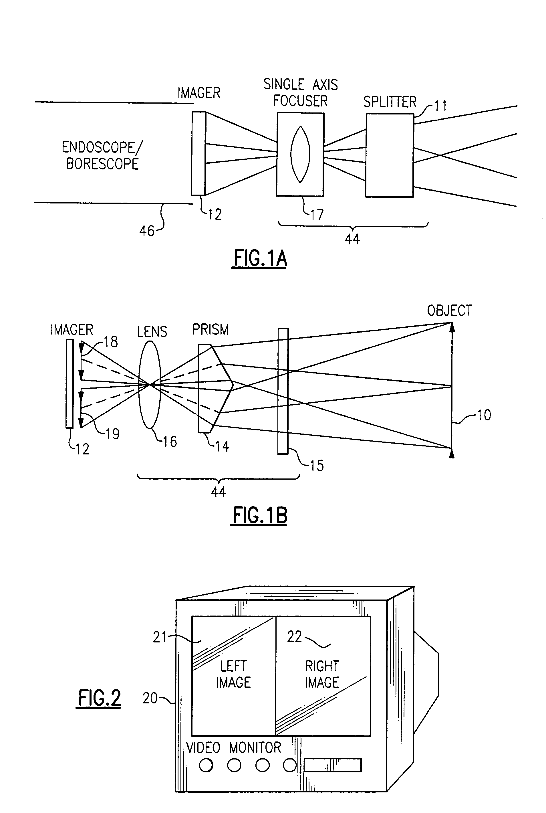
[0044]Referring to FIG. 1A, a probe 46 contains an imager 12. An optical system 44 includes an image splitter 11 and a single axis focuser 17. Image splitter 11 divides the field of view of focuser 17 into two overlapping fields of view which have different optical axes. The two fields of view are then focused on imager 12 by focuser 17.

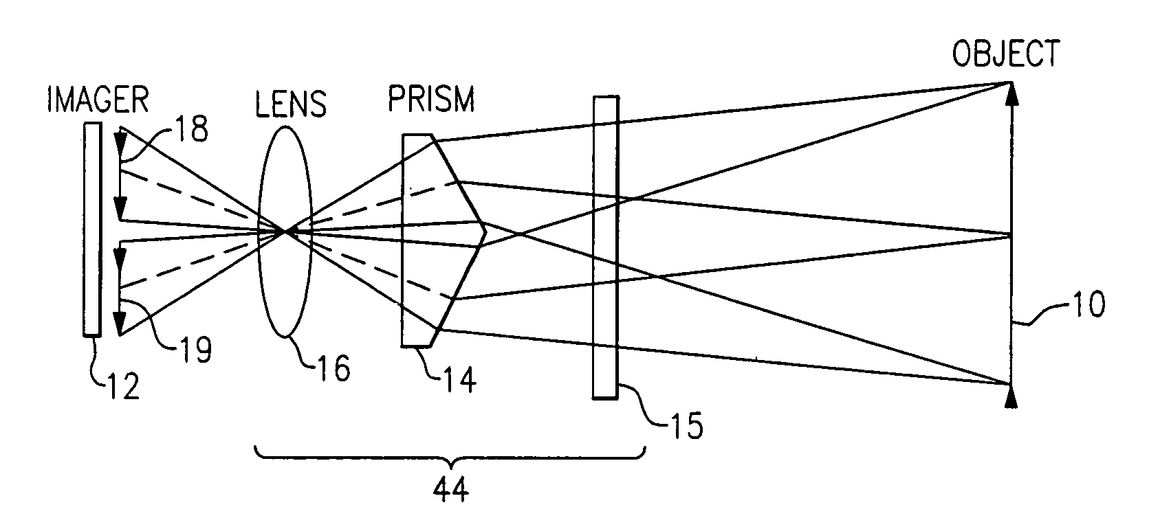
[0045]Referring to FIGS. 1B–2, an embodiment of optical system 44 shows an object 10 imaged onto imager 12 through a prism 14 and a lens assembly 16. The image of object 10 is split into two stereo image parts 18, 19 by prism 14. Prism 14 is preferably a refractive image-splitting prism, such as, for example, a wedge prism. Image parts 18 and 19 are then displayed on a monitor 20. The geometric dimensions of object 10 are then measured using at least one onscreen cursor along with a measurement process as discussed below. A transparent window 15 is optionally used to prevent fluids from contacting prism 14.

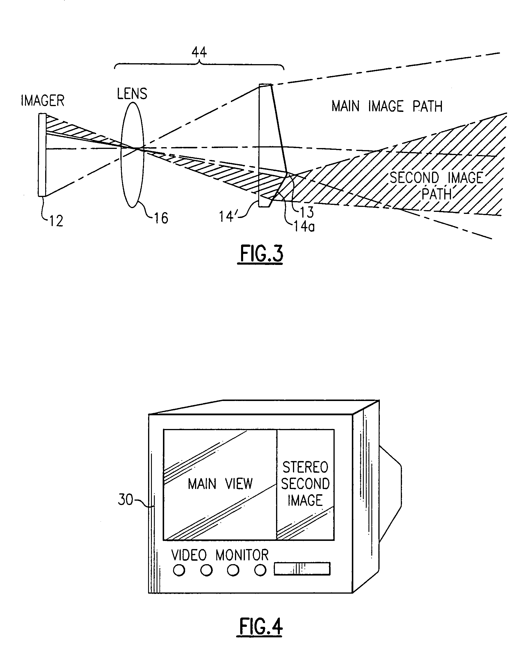
[0046]Using a single prism 14 to split the i...


PUM


Abstract

Two stereo images are created by splitting a single image into two images using a field of view dividing splitter. The two images can be displayed side by side so that they can be viewed directly using stereopticon technology, heads-up display, or other 3-D display technology, or they can be separated for individual eye viewing. The two images focus on one imager such that the right image appears on the right side of the monitor and the left image appears on the left side of the monitor. The view of the images is aimed to converge at a given object distance such that the views overlap 100% at the object distance. Measurement is done with at least one onscreen cursor.

Description

FIELD OF THE INVENTION[0001]This invention relates generally to the field of borescopes and endoscopes, and more particularly to a borescope / endoscope which provides a 3-D image from a single camera and lens system.BACKGROUND OF THE INVENTION[0002]Various devices are known in the prior art for realizing a full color video picture of a target situated within a remote cavity. Most devices of this type employ an external light source conveyed to the image head by fiber optic bundles together with a solid state image sensor and lens system positioned in the distal end of the insertion tube of a borescope / endoscope, referred to herein as a probe, connected to an external video display. A particularly compact head including a light source and solid state image sensor lens system of this type is shown in U.S. Pat. No. 4,491,865 (Danna et al.).[0003]Generally, in systems of this type, the fiber optic illumination bundle and the image sensor and optical system are disposed side by side in th...

Claims


Application Information

Patent Timeline
IPC IPC(8): G02B27/22
CPCA61B1/0005A61B1/00096A61B1/00181G02B23/2415A61B1/00193A61B1/05A61B1/00188
Inventor BENDALL, CLARK A.CHILEK, THEODORE A.KARPEN, THOMAS W.LIA, RAYMOND A.SALVATI, JON R.
Owner GE INSPECTION TECH LP
Why Eureka
Try Eureka