System for measuring wear in a grinding mill

a technology of grinding mill and wear measurement, which is applied in the field of grinding mill wear measurement system, can solve the problems of reducing personnel, reducing production efficiency, and entanglement of production time, and achieving the effect of reducing the thickness of wear

Inactive Publication Date: 2007-02-06
SLATER DENNIS +1
View PDF7 Cites 46 Cited by
  • Summary
  • Abstract
  • Description
  • Claims
  • Application Information

AI Technical Summary

Problems solved by technology

The stopping of one of these mills for inspection represents enormous losses in production time and high energy demand to start it up again.
As a wear plate gets thinner, the bolt heads holding it also wear down.
Although the systems of the prior art deserve undeniable merits, these systems provide warning when a wear plate is no longer protecting the shell of the mill and the mill must be shut down.
These failures can occur during a time of reduced personnel such as a night shift or a holiday.
The repair of the mill during these emergency situations is generally done by reduced-size crews and consequently, the mill is unproductive for a longer period than if the repairs would have been carried out during a planned shutdown.

Method used


Image

  • System for measuring wear in a grinding mill
  • System for measuring wear in a grinding mill
  • System for measuring wear in a grinding mill

Examples


Embodiment Construction

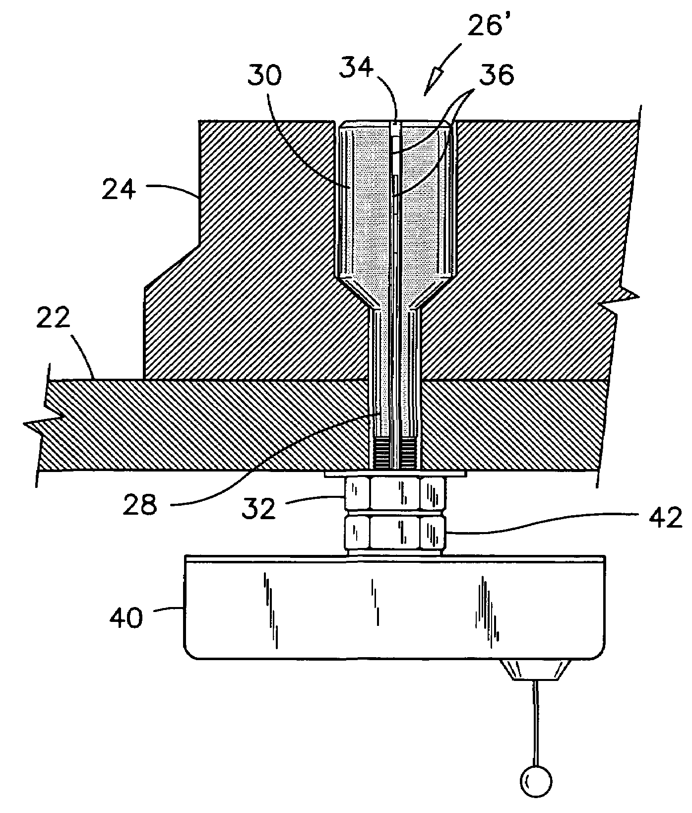
[0026]While this invention is susceptible of embodiment in many different forms, there is shown in the drawings and will be described in details herein one specific embodiment of a system for measuring wear in a grinding mill for grinding minerals, or a cement plant. The present disclosure is to be considered as an example of the principles of the invention and is not intended to limit the invention to the embodiment illustrated and described.

[0027]Although efforts have been made to limit the use of precise dimensions and exact geometric qualifiers, some narrow expressions remain in this disclosure and are used for convenience only to provide a better understanding of the present invention. Such dimensions and shapes can vary from one model of grinding mill to the other. Therefore the dimensions and geometric expressions mentioned herein should not be considered as being absolute and limiting.

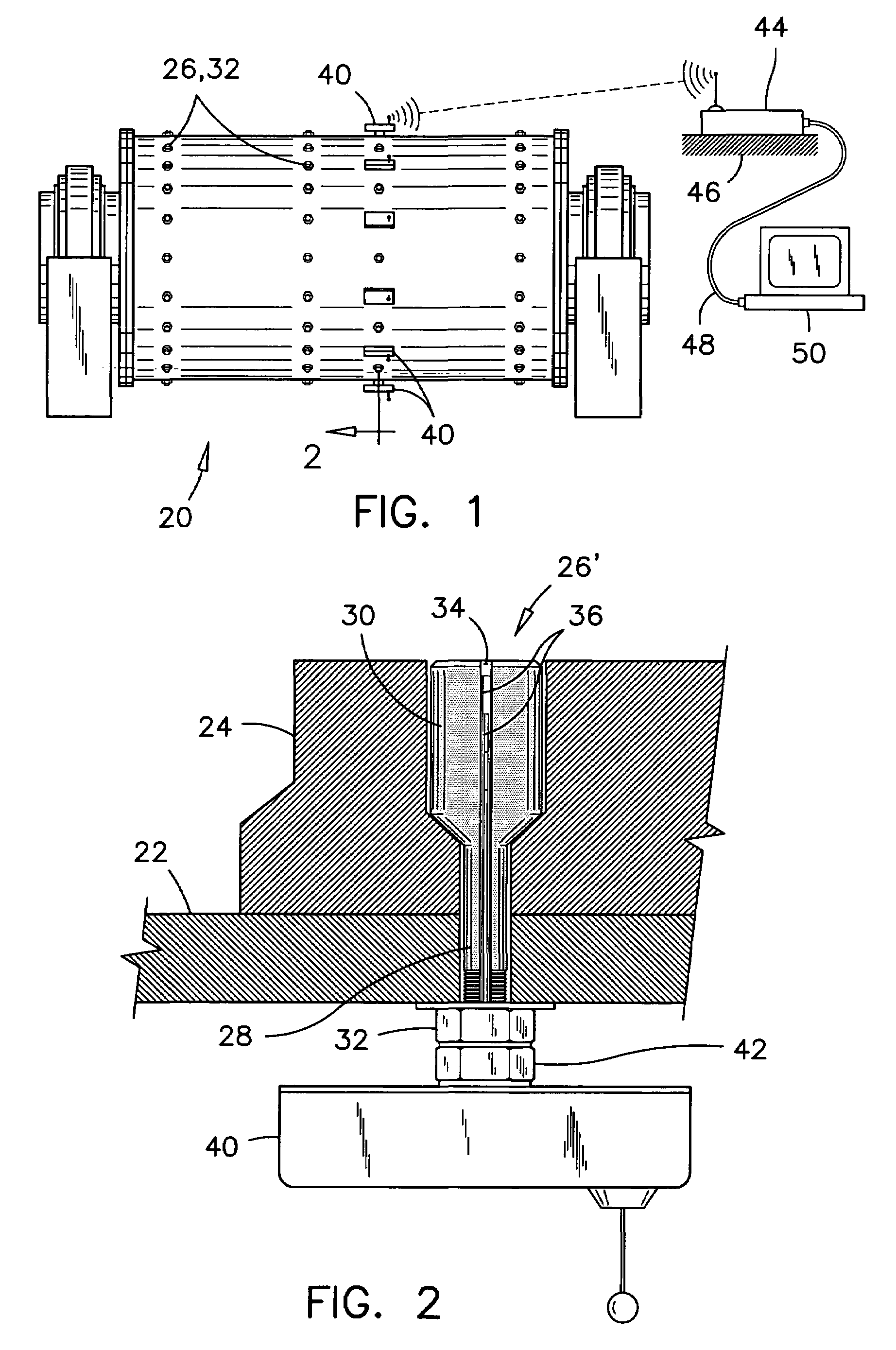
[0028]Referring to FIG. 1, a typical grinding mill 20 for grinding minerals is represented ...


PUM

PropertyMeasurementUnit
lengthaaaaaaaaaa
thicknessaaaaaaaaaa
frequencyaaaaaaaaaa

Abstract

The system for measuring wear in a grinding mill has at least one bolt passing through the shell and a wear plate. The bolt has an elongated oblong-shaped bolt head extending through the wear plate, flush with a surface of the wear plate. The bolt head is exposed to a same abrasion as the wear plate. The bolt has a groove there along and a plurality of wire loops embedded in that groove. Each wire loop extends to a distinct point along the bolt head, such as to form a ruler along the bolt head. A mobile transmitter-receiver is mounted to the stem of the bolt and is connected to the wire loops. The mobile transmitter-receiver has electronic circuitry therein for detecting broken loop conditions and for transmitting these conditions to a remote receiver where the conditions are related to degrees of wear on the wear plate.

Description

FIELD OF THE INVENTION[0001]This invention pertains to a system for measuring wear in a grinding mill for grinding minerals, and more particularly, it pertains to a self-contained measurement and wireless communication device for measuring wear in a grinding mill without stopping the mill.BACKGROUND OF THE INVENTION[0002]Mining companies grind several thousand tons of ore rocks per days. Generally, the grinding mills used for this task consist of revolving drums which are lined with wear-resistant plates, to resist the abrasion of the ore rocks tumbling against their inside surfaces. These wear plates are replaced periodically when they reach a minimum thickness.[0003]The stopping of one of these mills for inspection represents enormous losses in production time and high energy demand to start it up again. Therefore, there has been numerous efforts made in the past to shorten the inspection time or to reduce inspection frequency to a minimum. For examples;[0004]U.S. Pat. No. 1,772,0...

Claims


Application Information

Patent Timeline
Patent Type & Authority Patents(United States)
IPC IPC(8): B02B5/02B02C13/00G01N3/32
CPCB02C17/1805B02C17/22G01N2203/0664B02C2210/01
Inventor SLATER, DENNISLANGIS, ANDRE
Owner SLATER DENNIS
Why Eureka
Try Eureka