

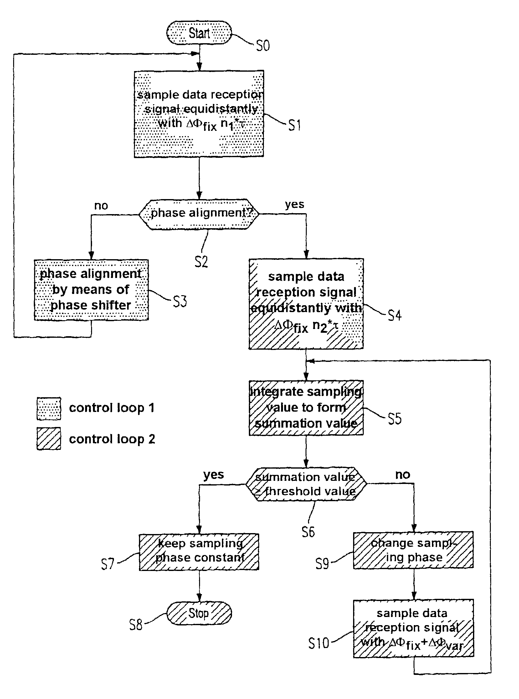
Method for sampling phase control
a sampling phase and control technology, applied in phase-modulated carrier systems, digital transmission, electrical equipment, etc., can solve the problems of disturbing jitter, frequency bandwidth limitation, and largely unknown transmission function h() of the transmission medium in many applications, and achieve the effect of reducing the bit error rate during sampling
- Summary
- Abstract
- Description
- Claims
- Application Information
AI Technical Summary
Benefits of technology
Problems solved by technology
Method used
Image

Examples
Embodiment Construction
[0058]The particulars shown herein are by way of example and for purposes of illustrative discussion of the embodiments of the present invention only and are presented in the cause of providing what is believed to be the most useful and readily understood description of the principles and conceptual aspects of the present invention. In this regard, no attempt is made to show structural details of the present invention in more detail than is necessary for the fundamental understanding of the present invention, the description taken with the drawings making apparent to those skilled in the art how the several forms of the present invention may be embodied in practice.
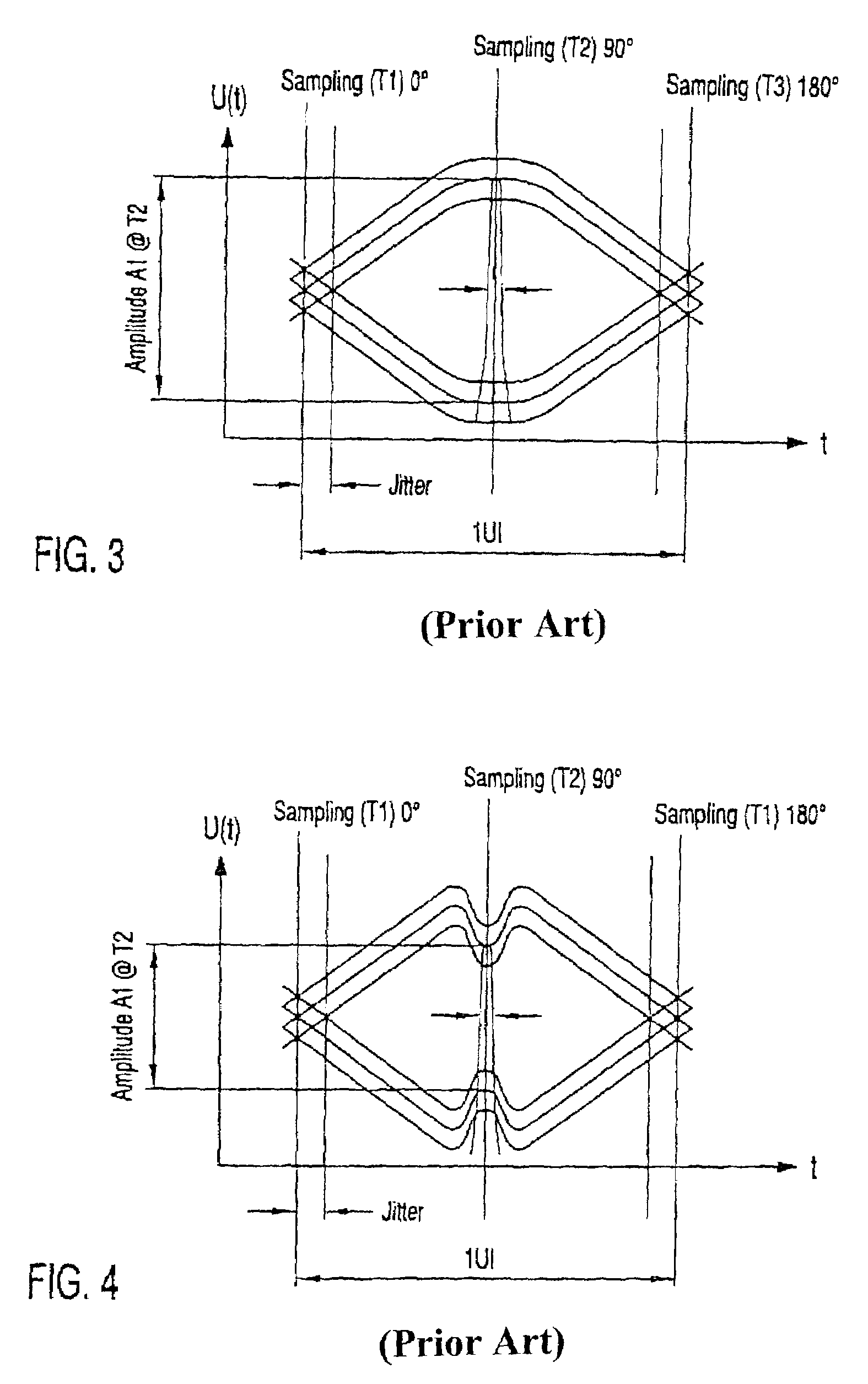
[0059]Referring to the drawings wherein like numerals represent like elements, FIG. 6 shows an eye diagram for elucidating the functional principle underlying the invention. Sampling of the data reception signal at the instant T2, i.e. phase-offset 90° with respect to the signal edge change, is not favorable on account of...
PUM
 Abstract
Description
Claims
Application Information