Devices for Dispersion Compensation, Beam Displacement, and Optical Switching

a technology of optical switching and dispersion compensation, applied in electromagnetic transmission, transmission, instruments, etc., can solve the problems of optical-electrical signal converters that are expensive, dominate the cost of the network, and the signal degradation and unacceptably high error ra

Inactive Publication Date: 2009-09-17
CIVCOM DEVICES & SYST
View PDF10 Cites 0 Cited by
  • Summary
  • Abstract
  • Description
  • Claims
  • Application Information

AI Technical Summary

Benefits of technology

[0079]There is further provided, according to an exemplary embodiment of the invention, an optical network comprising a dispersion compensation device according to an embodiment of the invention, wherein the control module

Problems solved by technology

Light traveling in optical networks often suffers from chromatic dispersion, or polarization mode dispersion, which can lead to degradation of signals and unacceptably high error rates.
But such optical-electrical signal converters are expensive, and may dominate the cost of the network, and may slow it down.
This limits the bandwidth that can be used, and may lim

Method used


Image

  • Devices for Dispersion Compensation, Beam Displacement, and Optical Switching
  • Devices for Dispersion Compensation, Beam Displacement, and Optical Switching
  • Devices for Dispersion Compensation, Beam Displacement, and Optical Switching

Examples


Embodiment Construction

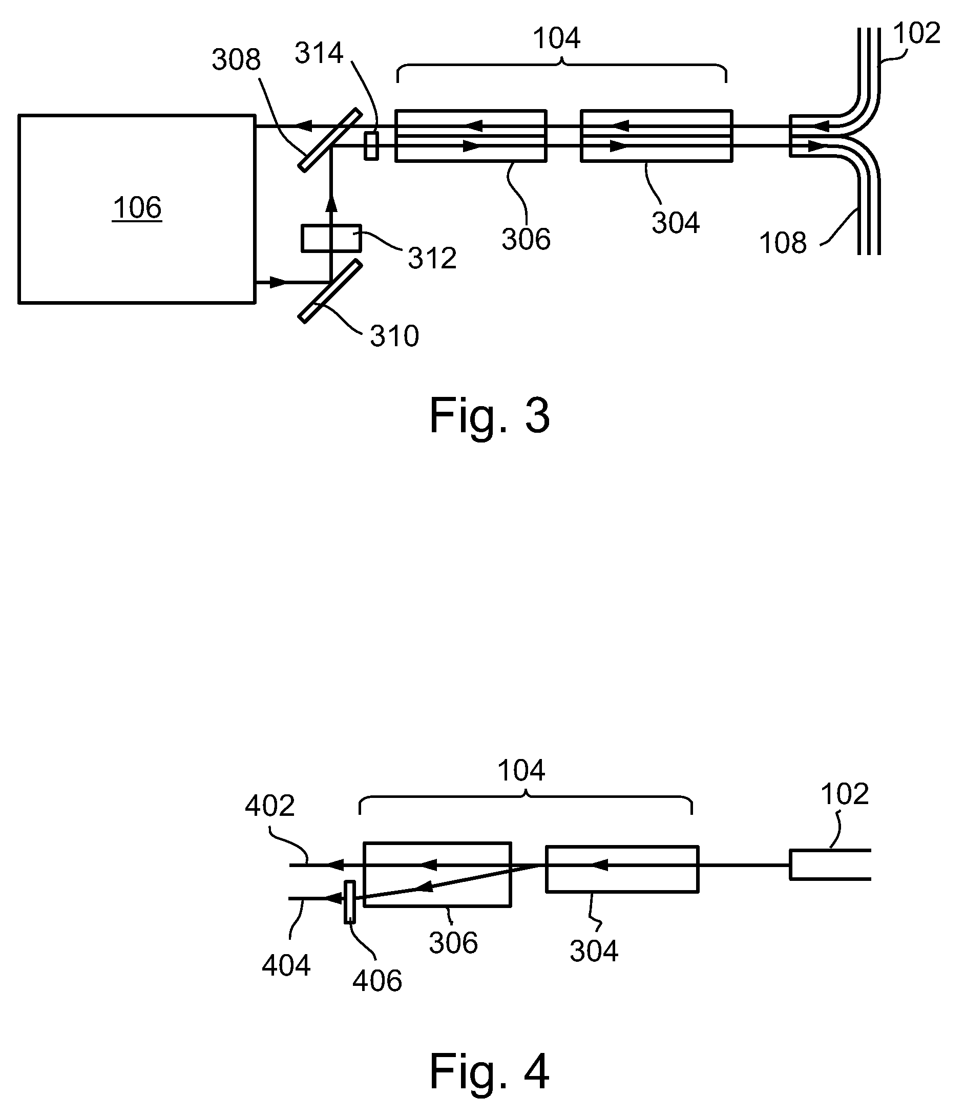
[0096]In describing the drawings, language will sometimes be used to the effect that a light beam undergoes a first event, for example an interaction with or passage through an optical element, followed in time by a second event. It should be understood that such language means that the second event would follow the first event from the point of view of an observer traveling along the light beam in the direction that the light is propagating. But at any given time, both of the events may be taking place simultaneously, to different parts of the beam.

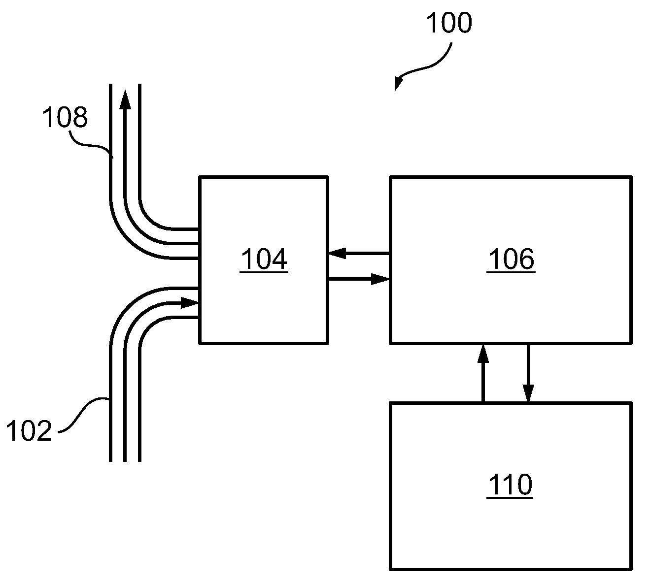
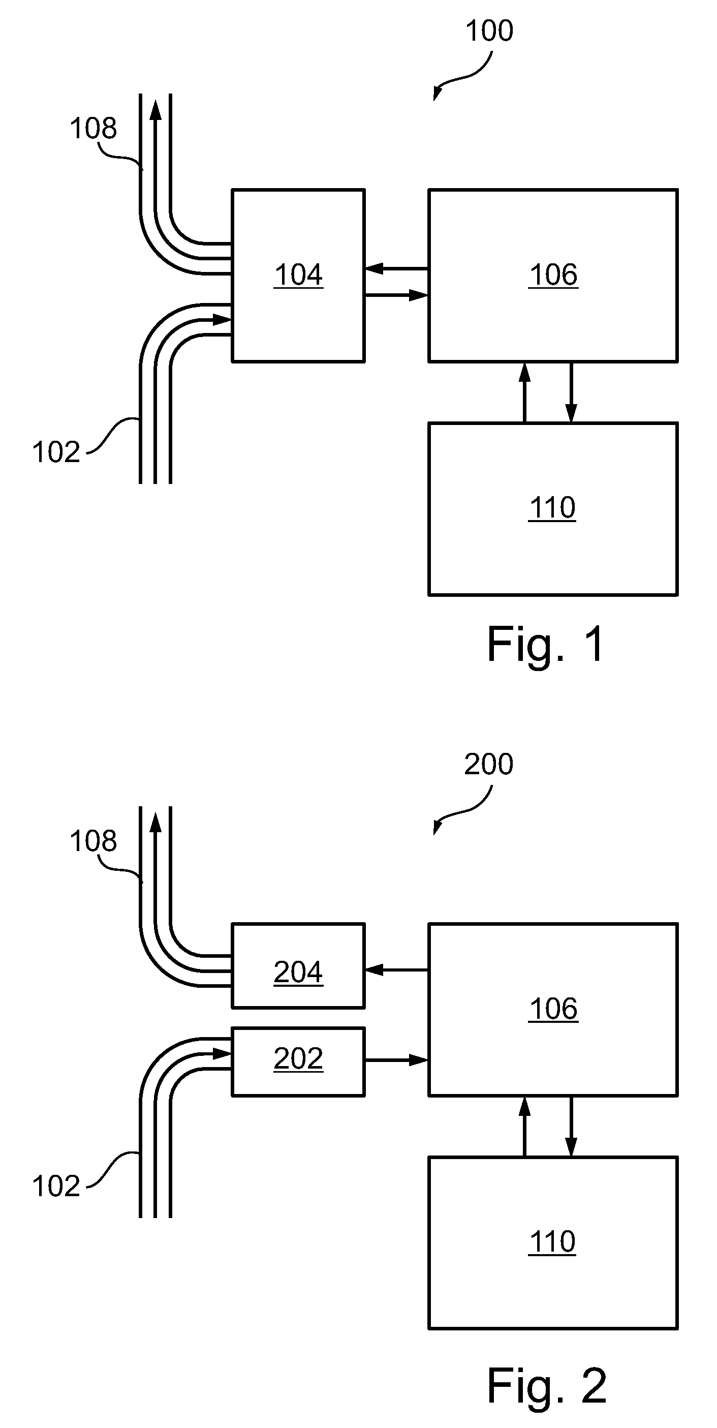
[0097]FIG. 1 schematically shows a dispersion compensation device 100, used for dispersion compensation in an optical network, according to an exemplary embodiment of the invention. We will first describe the overall architecture of the device, and then, starting with FIG. 5, describe how the dispersion compensation works.

[0098]Device 100 may be incorporated into an existing transceiver or transponder used in an optical network, or it ma...


PUM


Abstract

A method of laterally displacing at least a component of a light beam, the method comprising: a) directing the beam to enter a block of birefringent material at a first location, and at least the component of the beam to pass through the block on a first path to an exit location; and b) changing a polarization of the component of the beam after it has passed through the block, and directing it to pass back through the block from the previous exit location to a next exit location, following a next path oriented at changed angle due to its changed polarization state, at least one time; the component of the beam thereby being laterally displaced from the first location, when it exits the block a last time.

Description

RELATED APPLICATIONS[0001]This application is a Continuation of PCT application serial number PCT / IL2007 / 000984 filed on Aug. 7, 2007, which in turn claims the benefit under 35 USC 119(e) of U.S. Provisional Application No. 60 / 835,913, filed Aug. 7, 2006, both of which are incorporated herein by reference in their entirety.FIELD OF THE INVENTION[0002]The field of the invention is optical communication and processing.BACKGROUND OF THE INVENTION[0003]Light traveling in optical networks often suffers from chromatic dispersion, or polarization mode dispersion, which can lead to degradation of signals and unacceptably high error rates. In order for such networks to function, digital signals are converted into electrical signals, and back into fresh optical signals, at intervals short enough so that error rates are acceptably small. But such optical-electrical signal converters are expensive, and may dominate the cost of the network, and may slow it down. Methods of optically compensating...

Claims


Application Information

Patent Timeline
IPC IPC(8): G02B27/28
CPCG02B27/283
Inventor GOLDENBERG, EFRAIMGERSON, YUVALAMINOV, VYACHESLAV
Owner CIVCOM DEVICES & SYST
Why Eureka
Try Eureka