Self-adaptive receivers not requiring FEC feedback

a receiver and self-adaptive technology, applied in the field of optical communication, can solve the problems of dbpsk transmission system with 1.5-2 db worse receiver sensitivity than dbpsk transmission system, transmitter and receiver are significantly more complex than a traditional dbpsk transmitter, and the observed characteristic may be maximized or minimized, the effect of improving performan

Active Publication Date: 2014-02-25
LUMENTUM TECH UK LTD
View PDF13 Cites 0 Cited by
  • Summary
  • Abstract
  • Description
  • Claims
  • Application Information

AI Technical Summary

Benefits of technology

[0047]For example, the value for the characteristics of the receiver may be determined by observing a characteristic of a detector associated with the receiver, such as a ratio of the average photocurrents of the constructive and destructive ports of the detector. The observed characteristic of the detector may be mapped to a predetermined value for the characteristic of the receiver in a lookup table, which may be queried during operation of the receiver. Based on the predetermined value, the settings of the receiver may be adjusted to improve the performance of the receiver.
[0056]The value of the characteristic may be determined, for example, by minimizing a bit error rate (BER) associated with the optical signal. In other embodiments, the value may be determined by observing a characteristic of a detector associated with the receiver. The characteristic may represent, for example, an average photocurrent of the constructive port of the detector, an average photocurrent of the destructive port of the detector, a sum of the average photocurrents of the constructive and destructive ports of the detector, or a ratio of the average photocurrents of the constructive and destructive ports of the detector. The observed characteristic may be maximized or minimized.
[0057]Using the techniques described herein, the amount of optical filtering in the optical network can be estimated at the receiver and used for a variety of purposes. For example, using the estimated amount of optical filtering, the receiver can be configured for improved performance without relying on FEC.

Problems solved by technology

However, conventional DPSK transmission systems do not have good filter tolerance.
However, DQPSK transmission systems have approximately 1.5-2 dB worse receiver sensitivity than DBPSK transmission systems.
Furthermore, both the transmitter and the receiver are significantly more complex than a traditional DBPSK transmitter / receiver.
Thus, the interferometer may interfere a DPSK optical signal with itself.
At worst, the transmitter and detection unit may not be set up to provide FEC at all, and therefore this information is simply not available to the receiver.
Even when such FEC information is available to the receiver, using the FEC error signal can be an inefficient way to adjust receiver settings.
Additionally, as the BER approaches zero, small changes to the receiver settings may have a disproportionately large effect on the BER, or may have no observable effect at all.
In this case, the use of FEC to tune the receiver settings becomes difficult or impossible.
Accordingly, reliance on FEC can be an inefficient and undesirable characteristic of an optical receiver.

Method used


Image

  • Self-adaptive receivers not requiring FEC feedback
  • Self-adaptive receivers not requiring FEC feedback
  • Self-adaptive receivers not requiring FEC feedback

Examples


Embodiment Construction

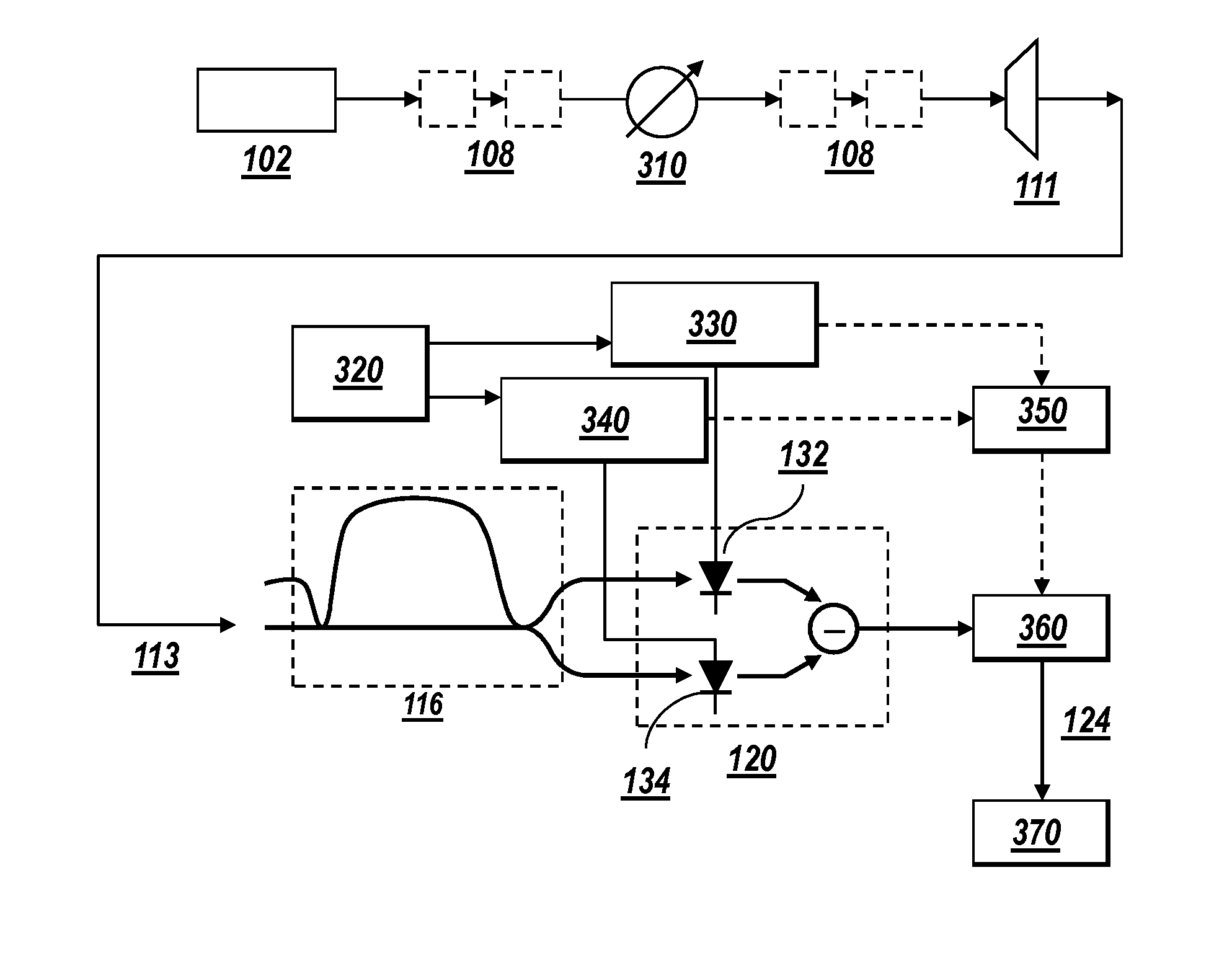
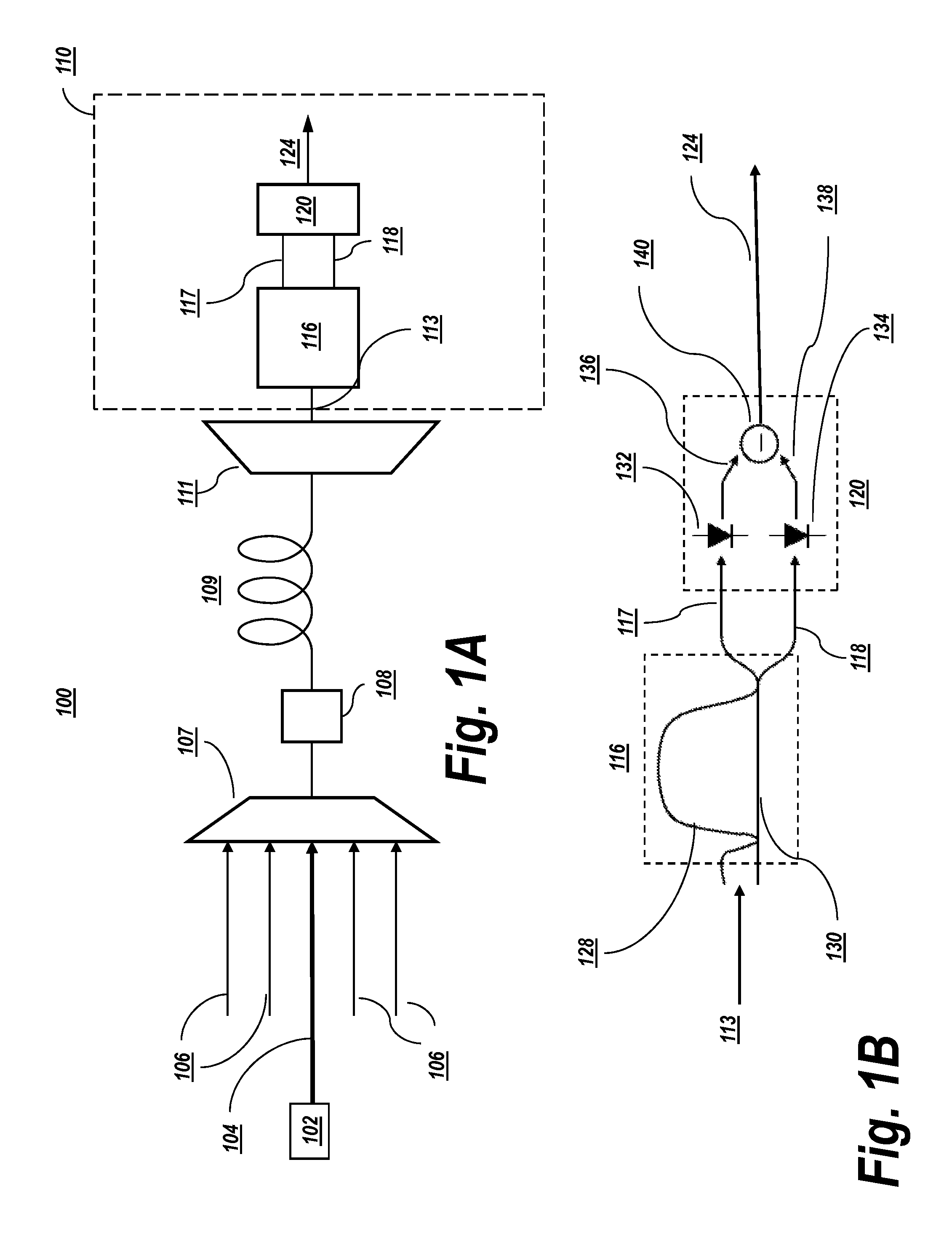
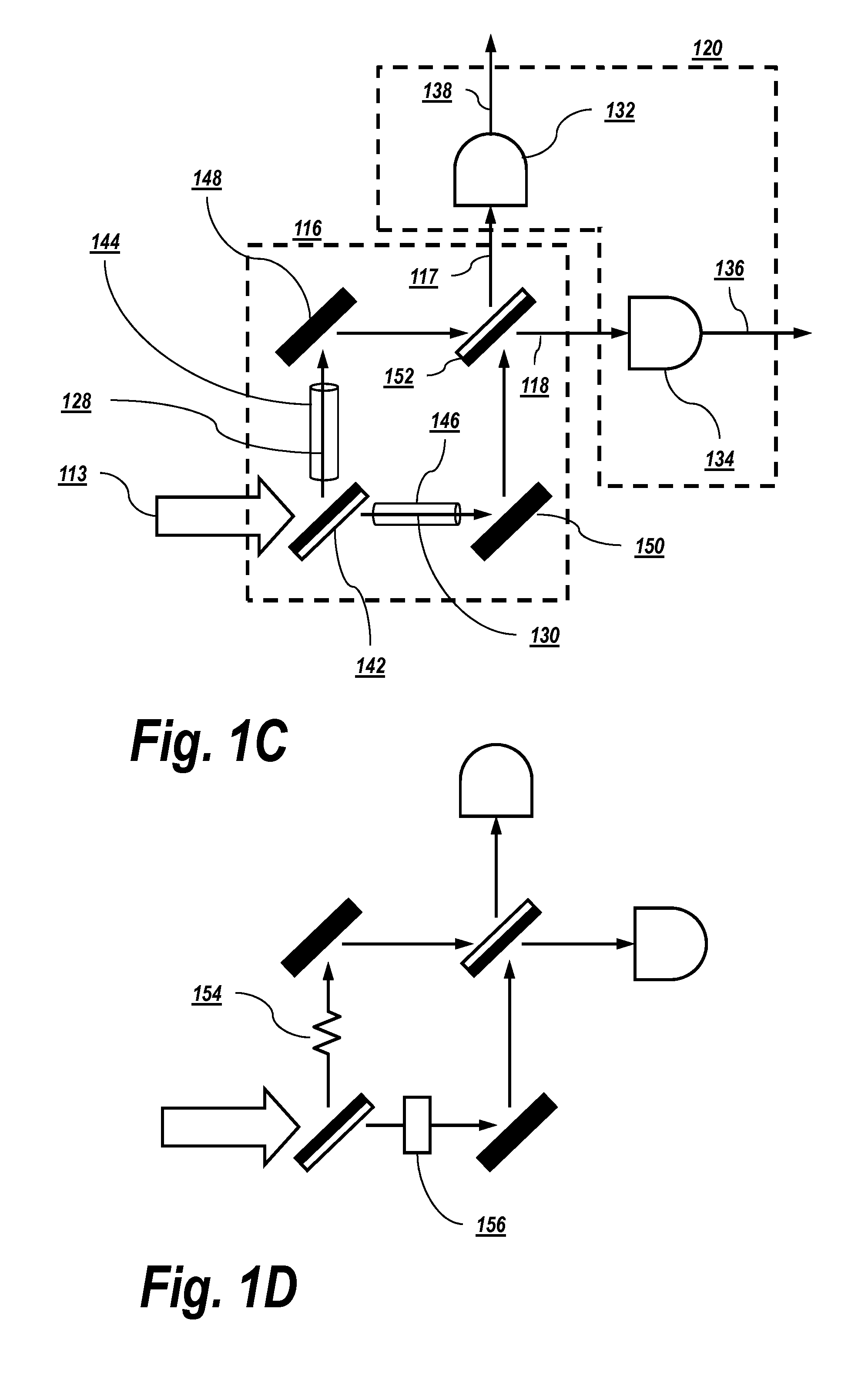
[0076]Optical communication networks rely on optical receivers to demodulate optical signals and convert the demodulated optical signal into an electrical signal. Optical receivers may be associated with one or more characteristics which can be made to vary during a transmission of an optical signal in order to improve the quality of the received signal. To achieve the optimum performance (i.e., minimum BER), the parameters of the receiver data recovery (for example, the DT voltage and the decision phase / timing) should be properly set. Another important receiver parameter that may be optimized, depending on the transmission line conditions, is the electrical bandwidth (BW) of the receiver.

[0077]The present invention estimates an amount of optical filtering (and hence, an optical bandwidth of an optical signal) in an optical communication network. The amount of the optical filtering may be representative of, for example, a narrowing or a widening of an optical bandwidth by one or mor...


PUM


Abstract

Optical communications networks rely on optical receivers to demodulate optical signals and convert the demodulated optical signal into an electrical signal. Optical receivers may be associated with one or more characteristics which can be made to vary during a transmission of an optical signal in order to improve the quality of the received signal. The present invention may determine a value for the characteristics based on an amount of optical filtering on a communications link which transmits the signal. The value for the characteristics of the receiver may be determined by observing a characteristic of a detector associated with the receiver, such as a ratio of the average photocurrents of the constructive and destructive ports of the detector. The observed characteristic of the detector may be mapped to a predetermined value for the characteristic of the receiver in a lookup table, which may be queried during operation of the receiver.

Description

RELATED APPLICATIONS[0001]This application claims priority to U.S. Provisional Application Ser. No. 61 / 346,690, filed on May 20, 2010. The contents of the aforementioned application is incorporated herein by reference.BACKGROUND OF THE INVENTION[0002]This invention generally relates to optical communications, and in particular to a method and system for determining the amount of optical filtering present in an optical communications network and setting values for receiver characteristics according to the amount of optical filtering.[0003]The backbone of point-to-point information transmission networks is a system of optically amplified dense wavelength division multiplex (DWDM) optical links. DWDM optical fiber transmission systems operating at channel rates of 40 Gb / s and higher are highly desirable because they potentially have greater fiber capacity and also have lower cost per transmitted bit compared to lower channel rate systems.[0004]The modulation format of 40 Gb / s DWDM tran...

Claims


Application Information

Patent Timeline
Patent Type & Authority Patents(United States)
IPC IPC(8): H04B10/61
CPCH04B10/677H04B10/69H04B10/0795H04B10/0799
Inventor MAMYSHEV, PAVELEDINBERG, JOEL R.
Owner LUMENTUM TECH UK LTD
Why Eureka
Try Eureka