
Tape measure system

a tape measure and tape measure technology, applied in the field of tape measures, can solve the problems of difficult control of the recoil of the tape measure, not as suitable for efficiently and not provide a convenient system for marking a measured obj

Inactive Publication Date: 2007-02-13
SMITH LESLIE G
View PDF31 Cites 37 Cited by
  • Summary
  • Abstract
  • Description
  • Claims
  • Application Information

AI Technical Summary

Benefits of technology

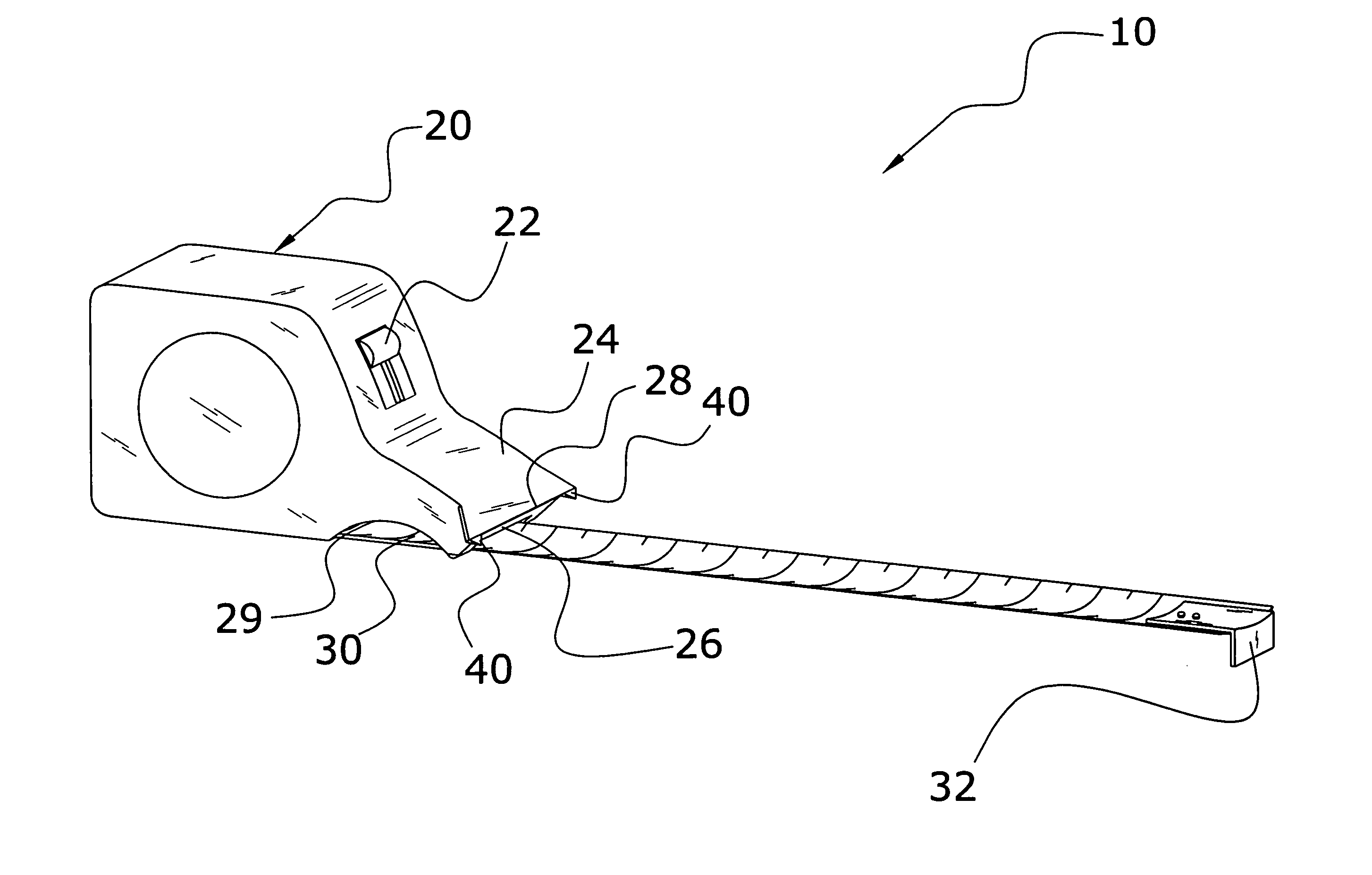
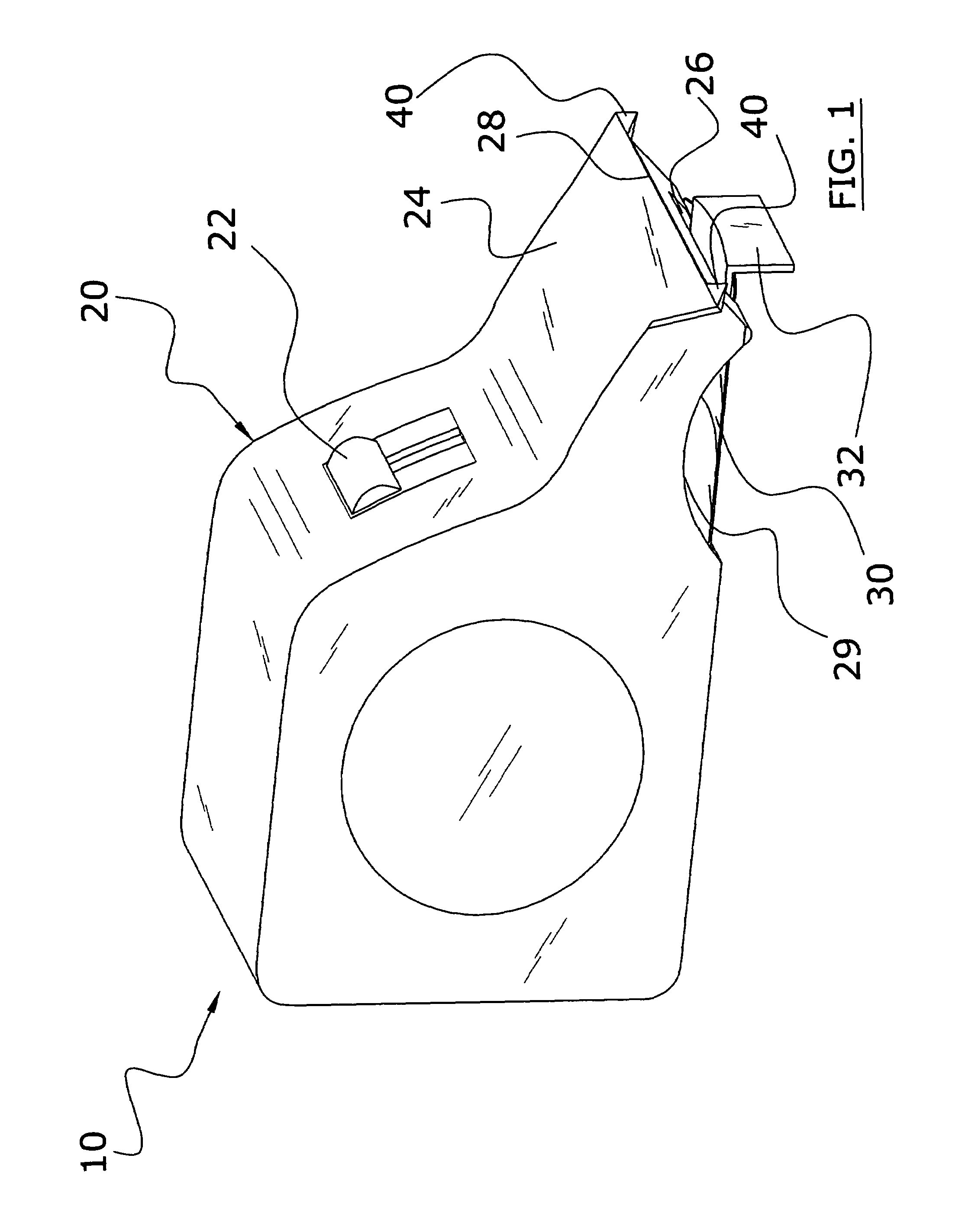
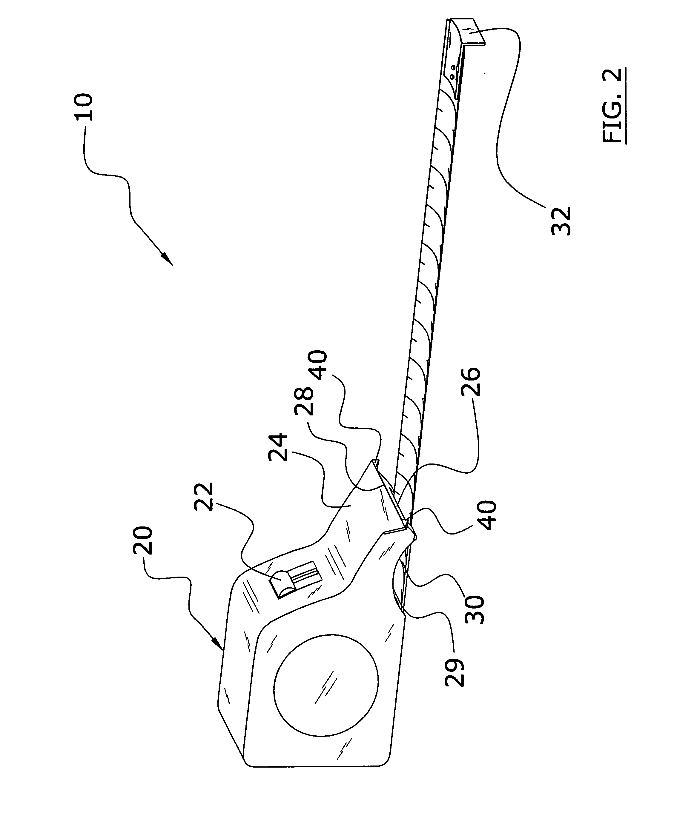
[0010]In view of the foregoing disadvantages inherent in the known types of tape measures now present in the prior art, the present invention provides a new tape measure system construction wherein the same can be utilized for efficiently marking a measured object.
[0012]To attain this, the present invention generally comprises a housing with a recoil unit containing a length of a tape measure, a dispensing neck extending from the housing for guiding and dispensing the tape measure, and wherein the dispensing neck includes a guide edge for marking a surface of a measured object. A pair of teeth extend from the dispensing neck for selectively engaging and marking the surface of the measured object. The dispensing neck includes a recessed portion exposing a portion of the tape measure for allowing frictional engagement of the tape measure by the user.
[0016]A second object is to provide a tape measure system for efficiently marking a measured object.
[0017]Another object is to provide a tape measure system that allows a user to control the retraction velocity of the tape measure.

Problems solved by technology

One problem with conventional tape measures is that they do not provide a convenient system for marking a measured object.
Another problem with conventional tape measures is that they are difficult to control the recoil of the tape measure.
While these devices may be suitable for the particular purpose to which they address, they are not as suitable for efficiently marking a measured object.
Conventional tape measures do not provide a convenient system for marking a measured object and also are inconvenient for controlling the recoil velocity of a tape measure.

Method used


Image

  • Tape measure system
  • Tape measure system
  • Tape measure system

Examples


Embodiment Construction

A. Overview

[0035]Turning now descriptively to the drawings, in which similar reference characters denote similar elements throughout the several views, FIGS. 1 through 8b illustrate a tape measure system 10, which comprises a housing 20 with a recoil unit 21 containing a length of a tape measure 30, a dispensing neck 24 extending from the housing 20 for guiding and dispensing the tape measure 30, and wherein the dispensing neck 24 includes a guide edge 28 for marking a surface of a measured object. A pair of teeth 40 extend from the dispensing neck 24 for selectively engaging and marking the surface of the measured object. The dispensing neck 24 includes a recessed portion 29 exposing a portion of the tape measure 30 for allowing frictional engagement of the tape measure 30 by the user.

B. Housing and Recoil Unit

[0036]FIGS. 1 through 8b illustrate an exemplary housing 20. The housing 20 includes a recoil unit 21 that receives and dispenses a length of a tape measure 30. The recoil un...


PUM


Abstract

A tape measure system for efficiently marking a measured object. The tape measure system includes a housing with a recoil unit containing a length of a tape measure, a dispensing neck extending from the housing for guiding and dispensing the tape measure, and wherein the dispensing neck includes a guide edge for marking a surface of a measured object. A pair of teeth extend from the dispensing neck for selectively engaging and marking the surface of the measured object. The dispensing neck includes a recessed portion exposing a portion of the tape measure for allowing frictional engagement of the tape measure by the user.

Description

CROSS REFERENCE TO RELATED APPLICATIONS[0001]Not applicable to this application.STATEMENT REGARDING FEDERALLY SPONSORED RESEARCH OR DEVELOPMENT[0002]Not applicable to this application.BACKGROUND OF THE INVENTION[0003]1. Field of the Invention[0004]The present invention relates generally to tape measures and more specifically it relates to a tape measure system for efficiently marking a measured object.[0005]2. Description of the Related Art[0006]Any discussion of the prior art throughout the specification should in no way be considered as an admission that such prior art is widely known or forms part of common general knowledge in the field.[0007]Tape measures have been in use for years. Typically, a conventional tape measure is comprised of a housing containing a recoil unit and a flexible tape measure that is dispensed from and stored within the housing by the recoil unit. One problem with conventional tape measures is that they do not provide a convenient system for marking a mea...

Claims


Application Information

Patent Timeline
Patent Type & Authority Patents(United States)
IPC IPC(8): G01B3/10
CPCG01B3/1084G01B2003/1007G01B2003/1089G01B2003/1046G01B2003/1048G01B2003/1043G01B3/1007G01B3/1043G01B3/1048G01B3/1046G01B3/1089
Inventor SMITH, LESLIE G.
Owner SMITH LESLIE G
Learn More