Method and system for defining the position of a fastener with a peen mark

a technology of fastener and peen mark, which is applied in the direction of center drills, manufacturing tools, transportation and packaging, etc., can solve the problems of increasing the time required for assembling the structure, increasing the cost of assembling the structure, and wasting time on the part of the pilot hole formation process, so as to facilitate the installation of the fastener

Active Publication Date: 2018-02-06
THE BOEING CO
View PDF18 Cites 1 Cited by
  • Summary
  • Abstract
  • Description
  • Claims
  • Application Information

AI Technical Summary

Benefits of technology

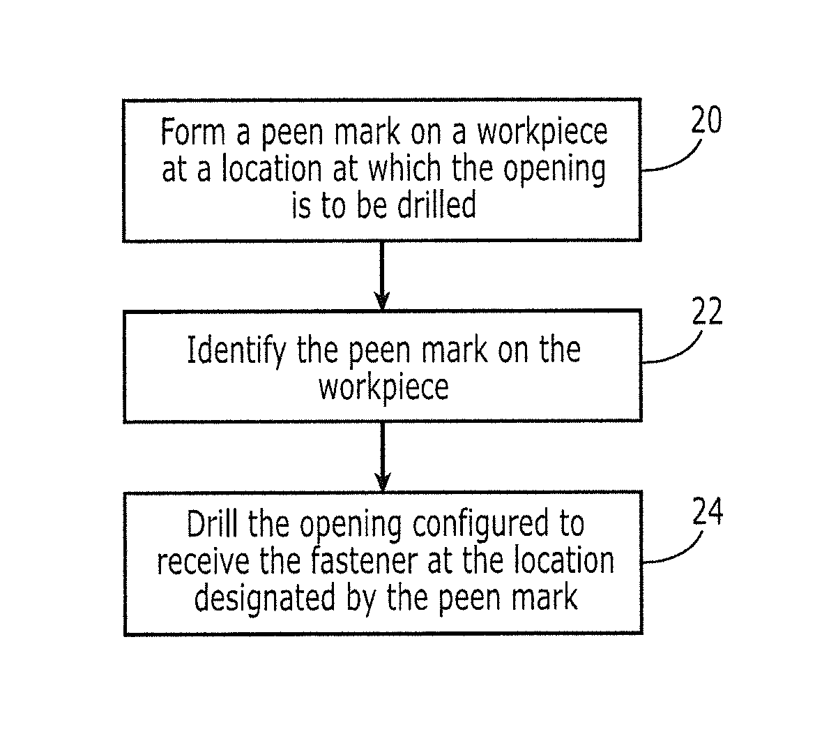
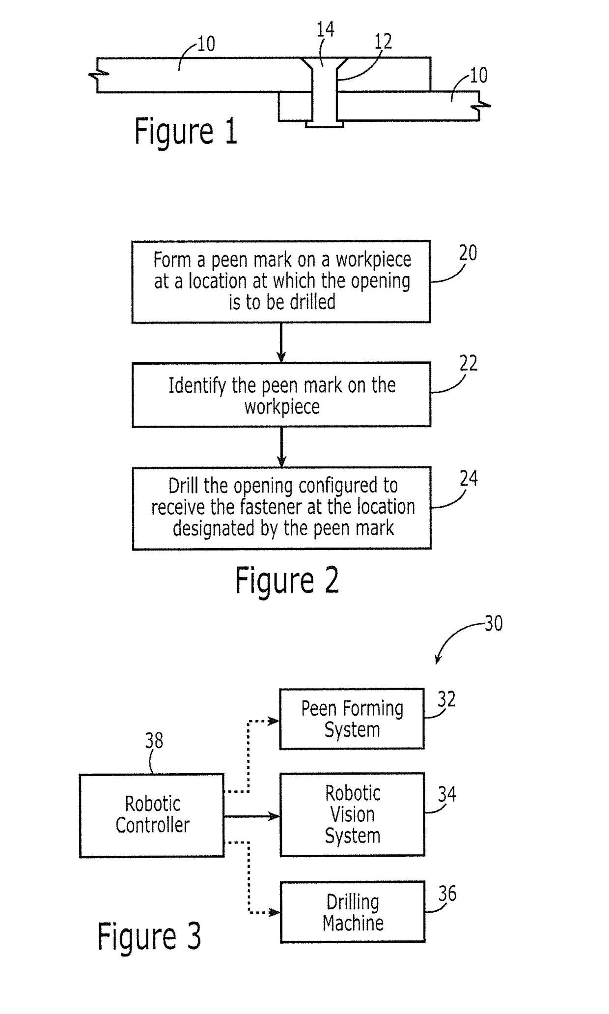
[0005]A method and system are provided in order to position and drill an opening for a fastener through one or more workpieces. The method and system of an example embodiment utilize a peen mark to identify the location of the opening for the fastener. As such, the location of a fastener may be marked in an efficient manner such that the overall process for drilling an opening for and then installing a fastener is facilitated.

Problems solved by technology

While pilot holes serve to effectively locate the predefined positions of the fasteners, the formation of the pilot holes may be a time-consuming process.
Since at least some parts include numerous fasteners, such as hundreds or thousands of fasteners, and, as such, require numerous pilot holes, the drilling of the pilot holes may require a substantial amount of time, thereby increasing the time required to assemble the structure and the costs associated with assembling the structure.

Method used


Image

  • Method and system for defining the position of a fastener with a peen mark
  • Method and system for defining the position of a fastener with a peen mark
  • Method and system for defining the position of a fastener with a peen mark

Examples


Embodiment Construction

[0024]Embodiments of the present disclosure now will be described more fully hereinafter with reference to the accompanying drawings, in which some, but not all embodiments are shown. Indeed, these embodiments may be embodied in many different forms and should not be construed as limited to the embodiments set forth herein; rather, these embodiments are provided so that this disclosure will satisfy applicable legal requirements. Like numbers refer to like elements throughout.

[0025]A method and system are provided in accordance with an example embodiment in order to precisely position and then drill one or more openings in a part such that respective fasteners may then be inserted through the openings in order to secure the part to another part. In this regard, structures frequently include a plurality of parts that are assembled and then secured to one another with a plurality of fasteners, such as rivets, bolts or the like. Although any of a wide variety of structures may be assemb...


PUM

PropertyMeasurementUnit
sizeaaaaaaaaaa
diameteraaaaaaaaaa
diametersaaaaaaaaaa

Abstract

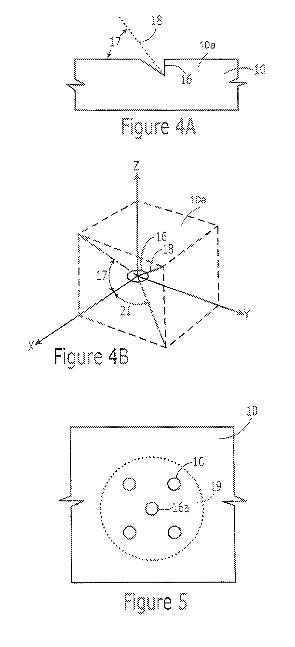
A method and system are provided to position and drill an opening for a fastener through one or more workpieces. In the context of a method, a peen mark is formed on a workpiece at a location at which the opening is to be drilled. The method also includes utilizing a robotic vision system to identify the peen mark on the workpiece and thereafter drilling the opening configured to receive the fastener at the location designated by the peen mark. In the context of a system, the system includes a dot peen marking system configured to form a peen mark on a workpiece at a location at which the opening is to be drilled. The system also includes a robot comprising a vision system configured to identify the peen mark on the workpiece and a drilling machine configured to drill the opening at the location designated by the peen mark.

Description

TECHNOLOGICAL FIELD[0001]An example embodiment of the present disclosure relates generally to the positioning and drilling of an opening for a fastener and, more particularly, to using a peen mark in order to position an opening for a fastener that is subsequently drilled in a workpiece.BACKGROUND[0002]Structures are oftentimes formed of a plurality of parts that are assembled and then secured with a plurality of fasteners, such as rivets or bolts. One example of such a structure is an aircraft that includes hundreds or thousands of parts that are assembled and then secured with even more fasteners. In order to install the fasteners, openings must be defined in the assembled parts, such as by drilling openings through the assembled parts with the size, e.g., diameter, of the openings approximating, such as by being slightly larger than, the size of the fasteners. The fasteners may then be inserted through the respective openings in order to secure the assembled parts.[0003]In order ...

Claims


Application Information

Patent Timeline
Patent Type & Authority Patents(United States)
IPC IPC(8): B23B49/02B25H7/04B21J15/44B23B49/00B23B35/00B25J11/00B21J15/28B21J15/14B23Q17/24B25J19/02B23B51/00
CPCB23B49/02B21J15/142B21J15/28B21J15/44B23B35/00B23Q17/24B25H7/04B25J11/005B25J19/021B23B49/00B23B2215/04B23B51/0063B23Q17/2233Y10T408/21B23Q16/12Y10T29/49947Y10T29/5118
Inventor GHADIALY, HASAN A.GRUBE, ROBERT WILLIAMLARSEN, TY AABY
Owner THE BOEING CO
Why Eureka
Try Eureka