Track slot fastener

a technology of track slot and fastener, which is applied in the field of fasteners, can solve the problems of difficult replacement, difficult installation and use of devices, and the limitation of conventional track fasteners that can only be loaded from the end

Inactive Publication Date: 2007-02-13
NISSAN MOTOR CO LTD
View PDF133 Cites 81 Cited by
  • Summary
  • Abstract
  • Description
  • Claims
  • Application Information

AI Technical Summary

Problems solved by technology

These devices, however, can be difficult to install and use, which detracts from their desirability in consumer environments such as original equipment manufactured (OEM) vehicles such as pickup trucks, mini-vans, sport-utility vehicles or other vehicles.
Often, conventional track fasteners can only be loaded from an end of the track slot, because their design does not facilitate top down loading, and are thus difficult to replace if broken.
Also problematic, many of these fasteners have limited load capacities, such as fasteners available on roof racks, and are thus unsuitable for applications such as truck beds and cargo areas where heavier loads are placed.
These devices, however, often require a user to have a wrench to loosen or tighten the bolt, which detracts from their ease of use.

Method used


Image

  • Track slot fastener
  • Track slot fastener
  • Track slot fastener

Examples


first embodiment

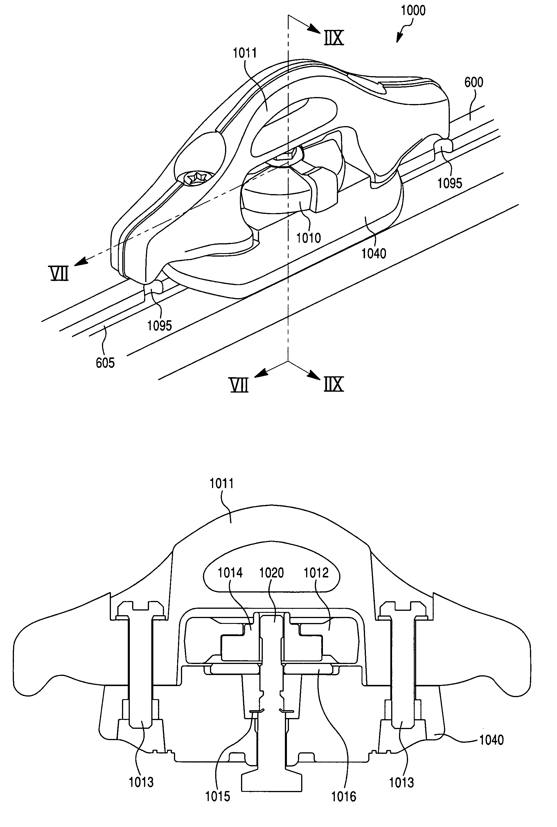
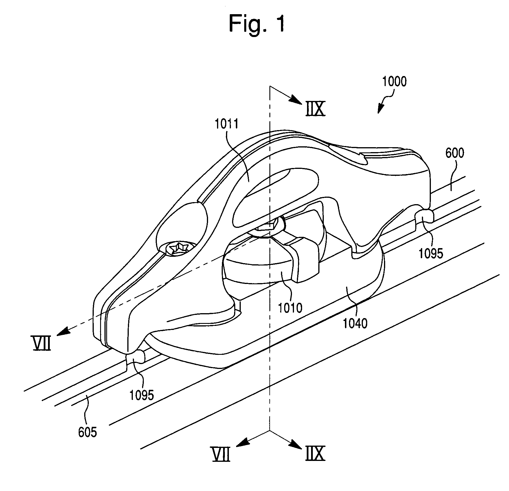
[0026]A fastener assembly 1000 retainable within a track slot 605 of a track 600 according to the present invention is shown in FIGS. 1 through 8. The fastener assembly 1000 includes a rotatable handle 1010, such as a thumb-wheel, which is shown best in FIGS. 5 and 6. The rotatable handle 1010 is disposed within an outer tie down 1011 for securing loads to the fastener assembly 1000. The rotatable handle 1010 is operably connected to a retainer 1050 by way of a shaft 1020. Retainer 1050 is configured to function in conjunction with a pressure plate 1040 to apply a mechanical clamping force on the track 600 when in an engaged or locked configuration.

[0027]According to the first embodiment of the present invention as shown in FIG. 2, a plurality of projections 1090 are configured to extend from a bottom surface 1041 of pressure plate 1040. Preferably, the projections 1090 extend from a region located generally in the interior of the bottom surface 1041 of pressure plate 1040. In this ...

second embodiment

[0032]A fastener assembly 400 retainable within a track slot of a track 110 according to the present invention is shown in FIGS. 9 and 10. A portion of FIG. 9 viewed from plane X—X is shown in greater detail in FIG. 10. The fastener assembly 400 according to this embodiment includes a rotatable handle 410, such as a thumb-wheel, within an outer tie down 411 for securing loads to the fastener assembly 400. The rotatable handle 410 operates retainer 450 via shaft 420. A spring 430 is provided in a space between the rotatable handle 410 and a pressure plate 440, such that the spring 430 applies a vertical force on a pin 443 with respect to the pressure plate 440. The pressure plate 440 is secured to the tie down 411 by screws 435.

[0033]To operate the fastener assembly 400, the rotatable handle 410 includes an angled running surface 445 interfacing pin 443. As the rotatable handle 410 is rotated between a locked position and a released position, the angled running surface 445 vertically...


PUM


Abstract

A fastener assembly secures loads to a track in a truck bed and is retainable within a track slot of the track. The fastener assembly may include a retainer adapted to fit at least partly within a track slot and a rotatable handle operating on the retainer, the rotatable handle being rotatable between at least an engagement position and a release position. A pressure applicator is positioned between the track and the rotatable handle, the pressure applicator having a bottom surface for applying a pressure on a top surface of the track in response to the position of the rotatable handle. The pressure applicator includes at least one projection projecting from an interior region of the bottom surface and adapted to engage a positioning scallop of the track.

Description

CORRESPONDING RELATED APPLICATIONS[0001]The present application is a continuation in part of U.S. application Ser. No. 10 / 336,033 filed on Jan. 3, 2003 and now U.S. Pat. No. 6,827,531, which is incorporated by reference herein in its entirety.[0002]Additionally, the present application is related to U.S. application Ser. No. 09 / 874,979 filed on Jun. 7, 2001 and now U.S. Pat. No. 6,846,140, and U.S. application Ser. No. 10 / 109,051 filed on Mar. 29, 2002 by Mark D. Snyder et al. and now U.S. Pat. No. 6,712,568, which are incorporated by reference herein in their entirety.BACKGROUND OF THE INVENTION[0003]1. Field of the Invention[0004]The present invention relates generally to fasteners for securing loads to a track, and more particularly, to adjustable fasteners for securing loads to a track mounted in or near a truck bed.[0005]2. Background of the Invention[0006]Fasteners for securing loads to framing, tracks, and channels have been commercially available for some time. Some conventi...

Claims


Application Information

Patent Timeline
Patent Type & Authority Patents(United States)
IPC IPC(8): B60P7/08B60P7/06B61D45/00F16B2/12F16B21/04F16B37/04
CPCB60P7/0815F16B37/045B61D45/001
Inventor WOMACK, DARRENBOWES, WILLIAM G.
Owner NISSAN MOTOR CO LTD
Why Eureka
Try Eureka