BRDF analyzer

a reflection distribution and analyzer technology, applied in the direction of instrumentation, picture signal generators, material analysis, etc., can solve the problems of inability to measure the brdf of real-world samples, high cost, and current techniques to do so

Active Publication Date: 2007-02-13
NEW YORK UNIV
View PDF2 Cites 61 Cited by
  • Summary
  • Abstract
  • Description
  • Claims
  • Application Information

AI Technical Summary

Problems solved by technology

One bottleneck to this process is the need to measure the BRDF of real-world samples.
Current techniques to do this are highly invasive, in that they require the sample to be placed in a specially lit environment [S. Marschner, S. Westin, E. Lafortune, K. Torrance, and D. Greenberg. Image-based BRDF Measurement Including Human Skin.
For some surfaces, such as living human skin, which cannot be placed by itself in an isolated measuring chamber, this is a difficult, tedious and expensive process.

Method used


Image

  • BRDF analyzer
  • BRDF analyzer
  • BRDF analyzer

Examples


Embodiment Construction

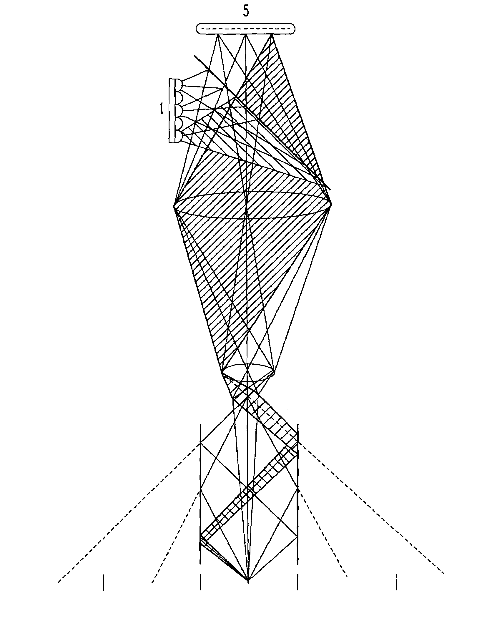
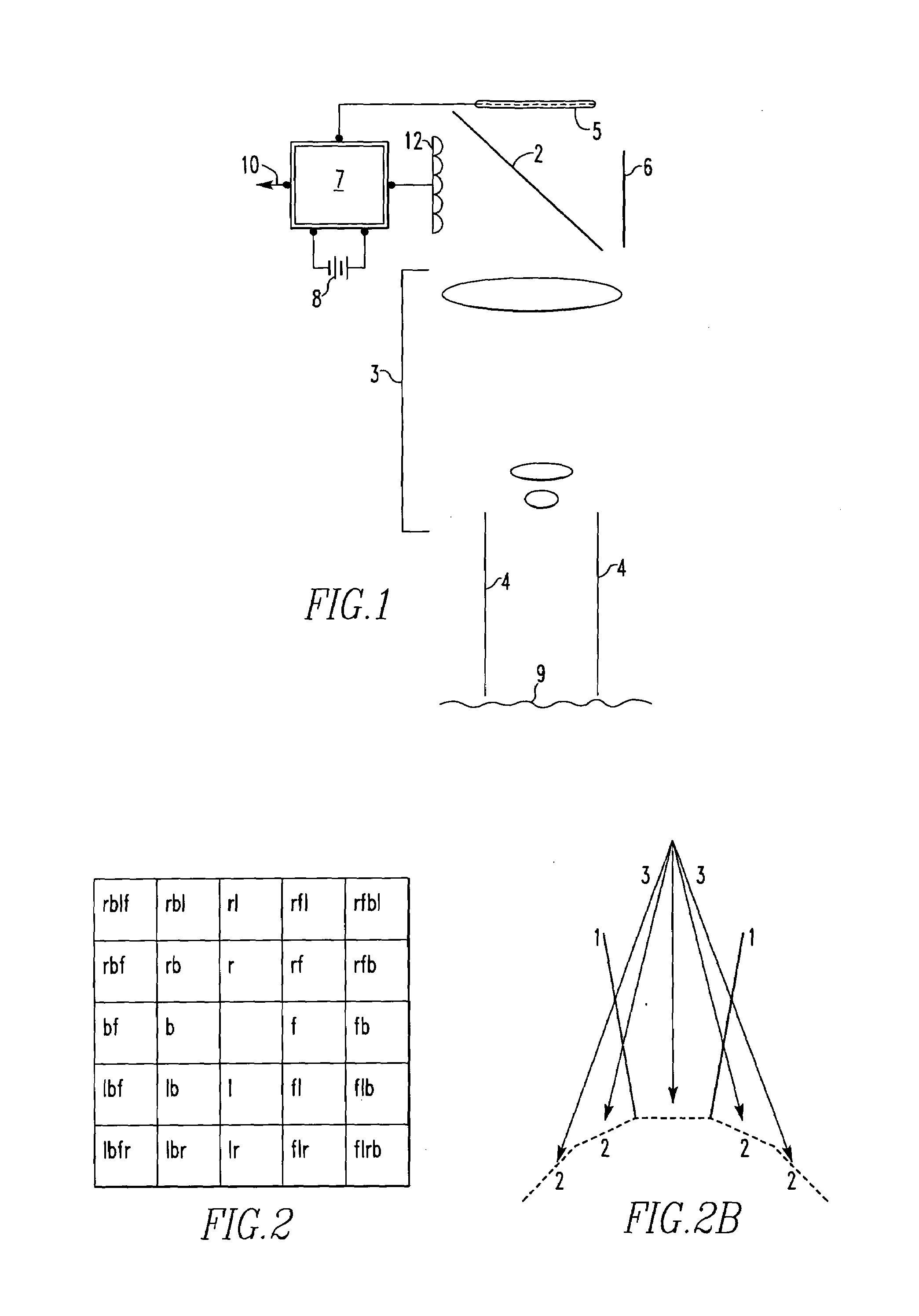
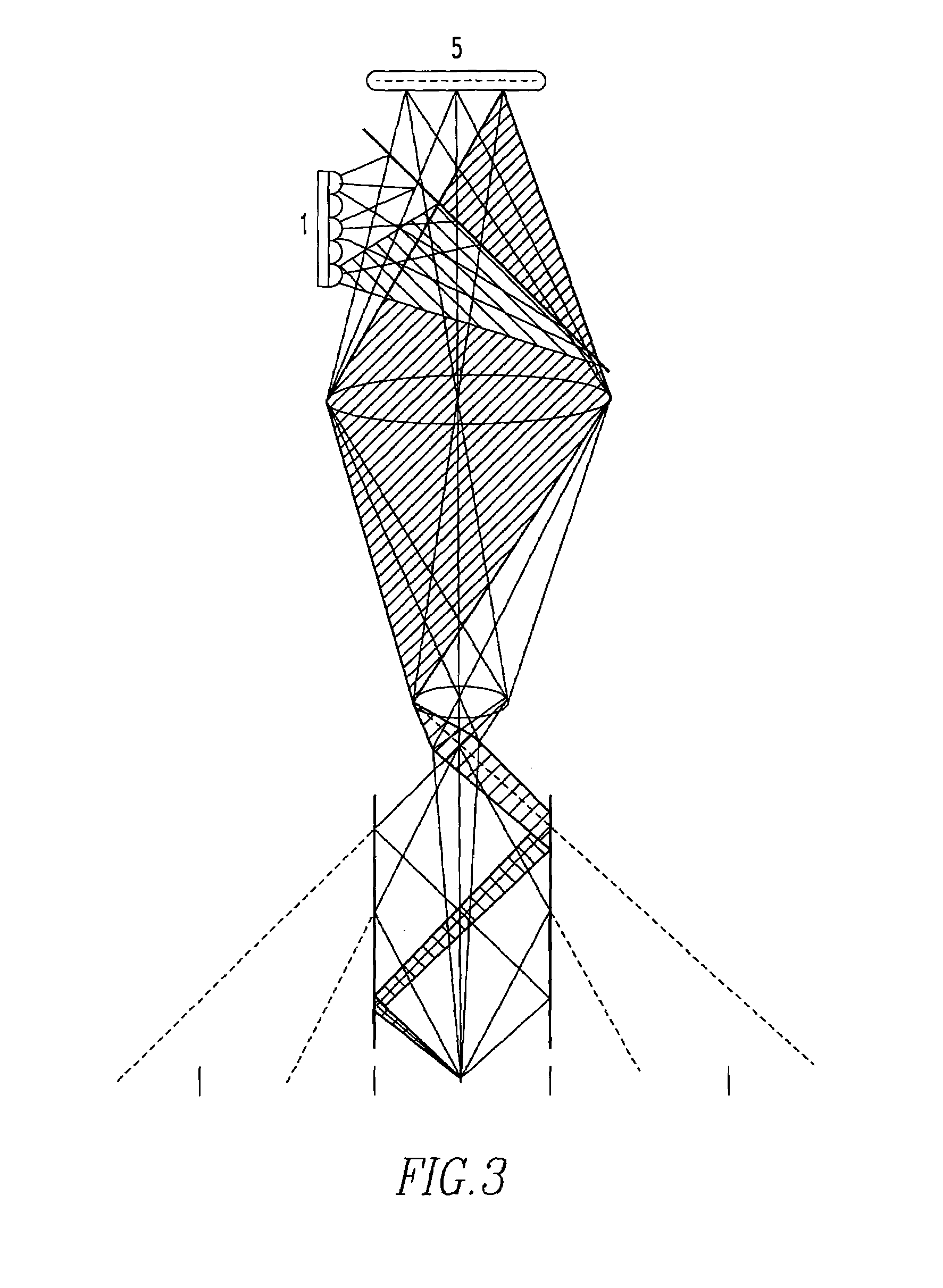
[0019]Referring now to the drawings wherein like reference numerals refer to similar or identical parts throughout the several views, and more specifically to FIGS. 1 and 4 thereof, there is shown an apparatus 10 for determining a bidirectional reflectance distribution function of a subject. The apparatus 10 comprises a light source 12 for producing light. The apparatus 10 comprises sensing means 14 for sensing the light. The apparatus 10 comprises means 16 for focusing the light between the light source 12 and the sensing means 14 and the subject. The apparatus 10 comprises a computer 7 connected to the sensing means 14 for measuring the bidirectional reflectance distribution function of the subject from the light sensed by the sensing means 14.

[0020]Preferably, the sensing means 14 includes a light absorbing wall 6 which absorbs unwanted light from the light source 12. The focusing means 16 preferably includes a hollow tube 4 lined with mirrors 24 through which light from light so...


PUM

PropertyMeasurementUnit
bidirectional reflectance distribution functionaaaaaaaaaa
bidirectional reflectance distributionaaaaaaaaaa
bidirectional reflectance functionaaaaaaaaaa

Abstract

An apparatus for determining a bidirectional reflectance distribution function of a subject. The apparatus includes a light source for producing light. The apparatus includes sensing means for sensing the light. The apparatus includes means for focusing the light between the light source and the sensing means and the subject. The apparatus includes a computer connected to the sensing means for measuring the bidirectional reflectance distribution function of the subject from the light sensed by the sensing means. The apparatus can include only one CCD camera for sensing the light. The apparatus can include means for taking sub-measurements of the subject with light from the light source without any physical movement between sub-measurements. A method for determining a bidirectional reflectance distribution function of a subject.

Description

[0001]This application claims the benefit of U.S. Provisional Application Nos.: 60 / 413,533 Sep. 25, 2002.[0002]This application is a continuation-in-part of copending application application Ser. No. 10 / 620,920 filed on Jul. 16, 2003.[0003]The nonprovisional application designated above, namely application Ser. No. 10 / 620,920, filed Jul. 16, 2003, claims the benefit of U.S. Provisional Application Nos.: 60 / 396,697 Jul. 17, 2002.FIELD OF THE INVENTION[0004]The present invention is related to determining a bidirectional reflectance distribution function of a subject. More specifically, the present invention is related to determining a bidirectional reflectance distribution function of a subject with a hollow tube lined with mirrors through which light from light source passes, reflecting zero or more times off of the mirrors.BACKGROUND OF THE INVENTION[0005]The way that any point on a surface interacts with light can be described by its Bidirectional Reflectance Distribution Function,...

Claims


Application Information

Patent Timeline
Patent Type & Authority Patents(United States)
IPC IPC(8): G01N21/47G01N21/55
CPCG01N21/55G01N2021/4711G01N2201/062G01N2201/0221G01N2021/556
Inventor PERLIN, KENNETH
Owner NEW YORK UNIV
Why Eureka
Try Eureka