

Microactuated head suspension with ring springs
a microactuated and head suspension technology, applied in the direction of maintaining the head carrier alignment, recording information storage, instruments, etc., can solve the problem that it is increasingly difficult for the motor and servo control system to quickly and accurately position the read/write head
- Summary
- Abstract
- Description
- Claims
- Application Information
AI Technical Summary
Problems solved by technology
Method used
Image

Examples
first embodiment
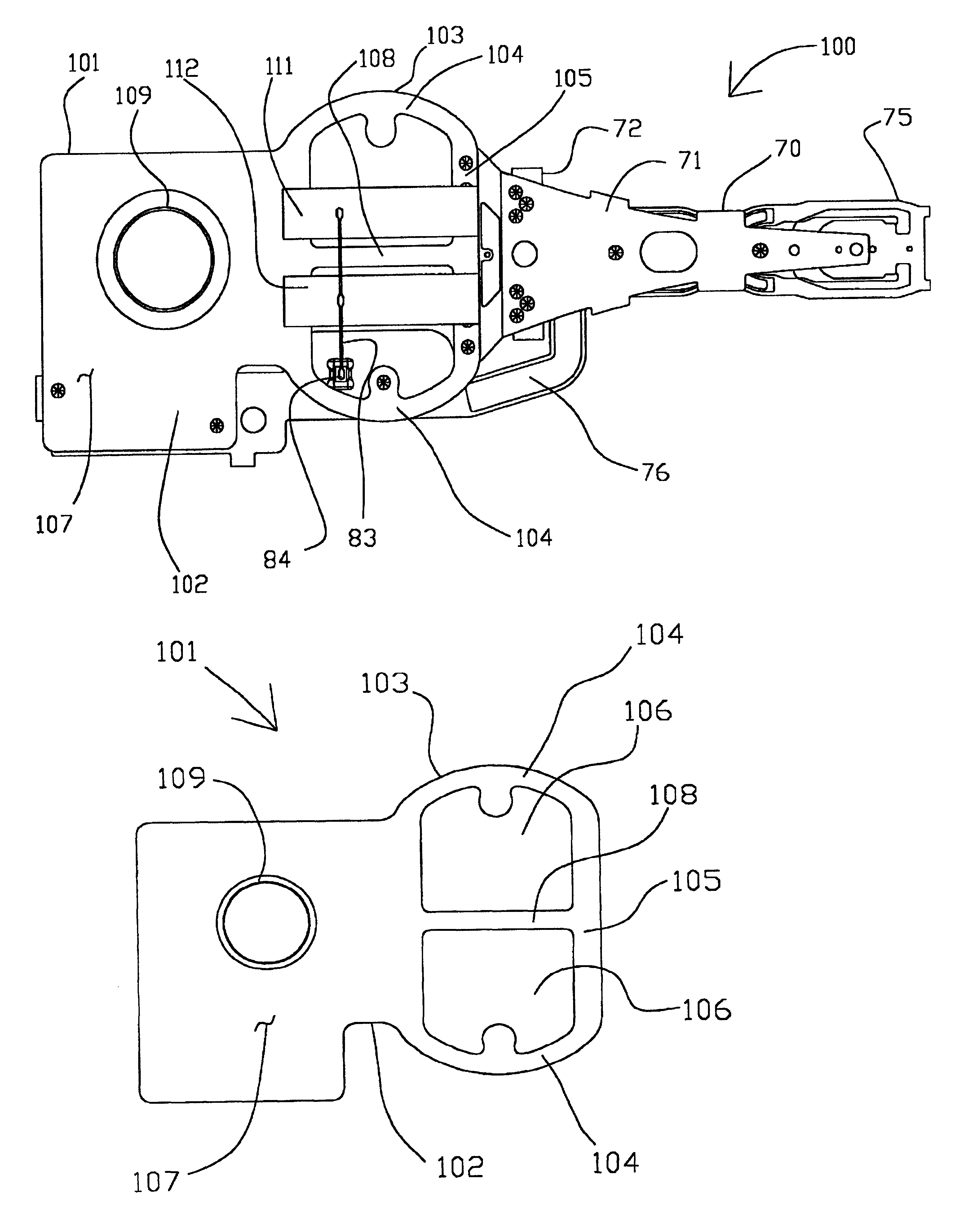
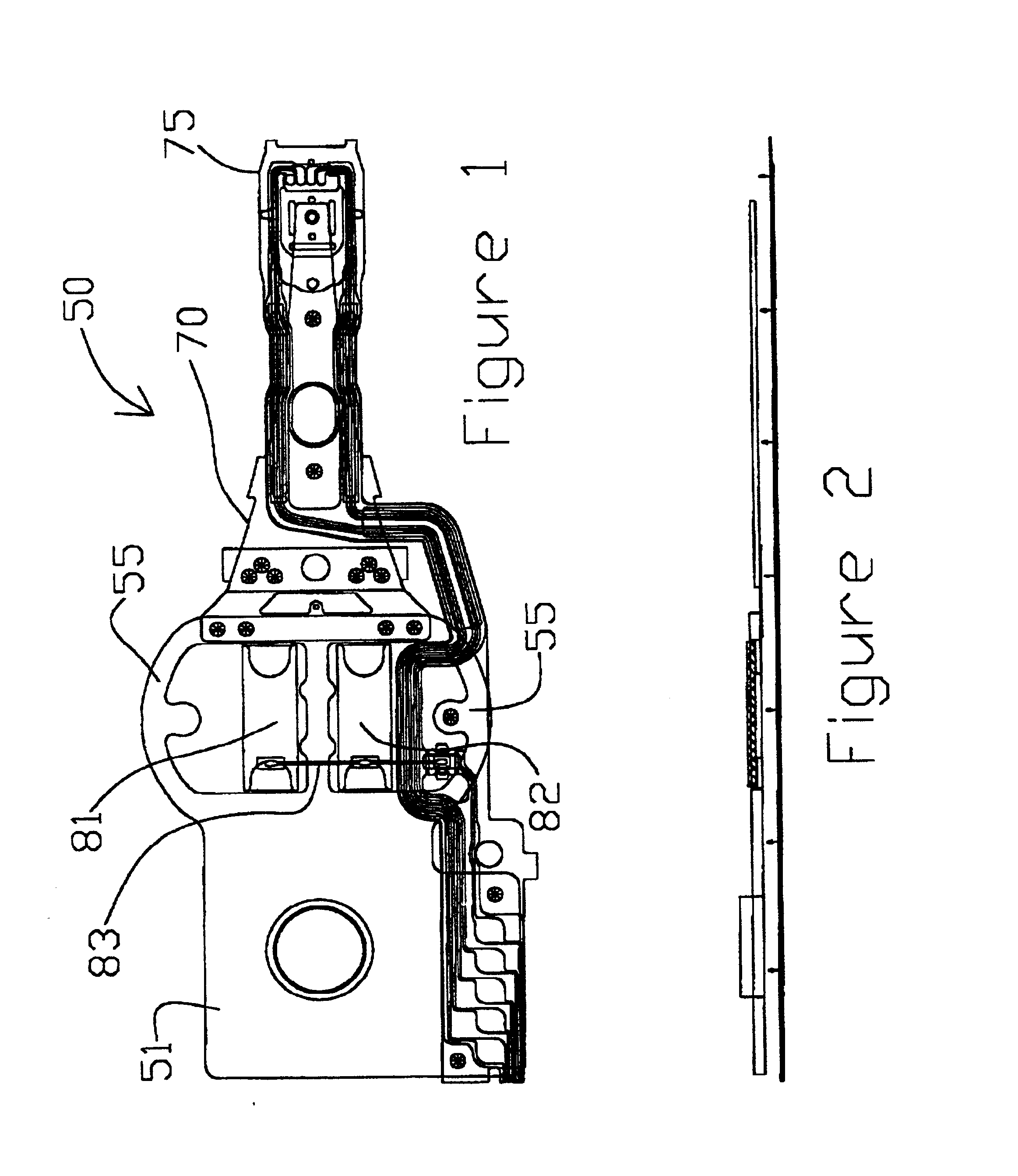
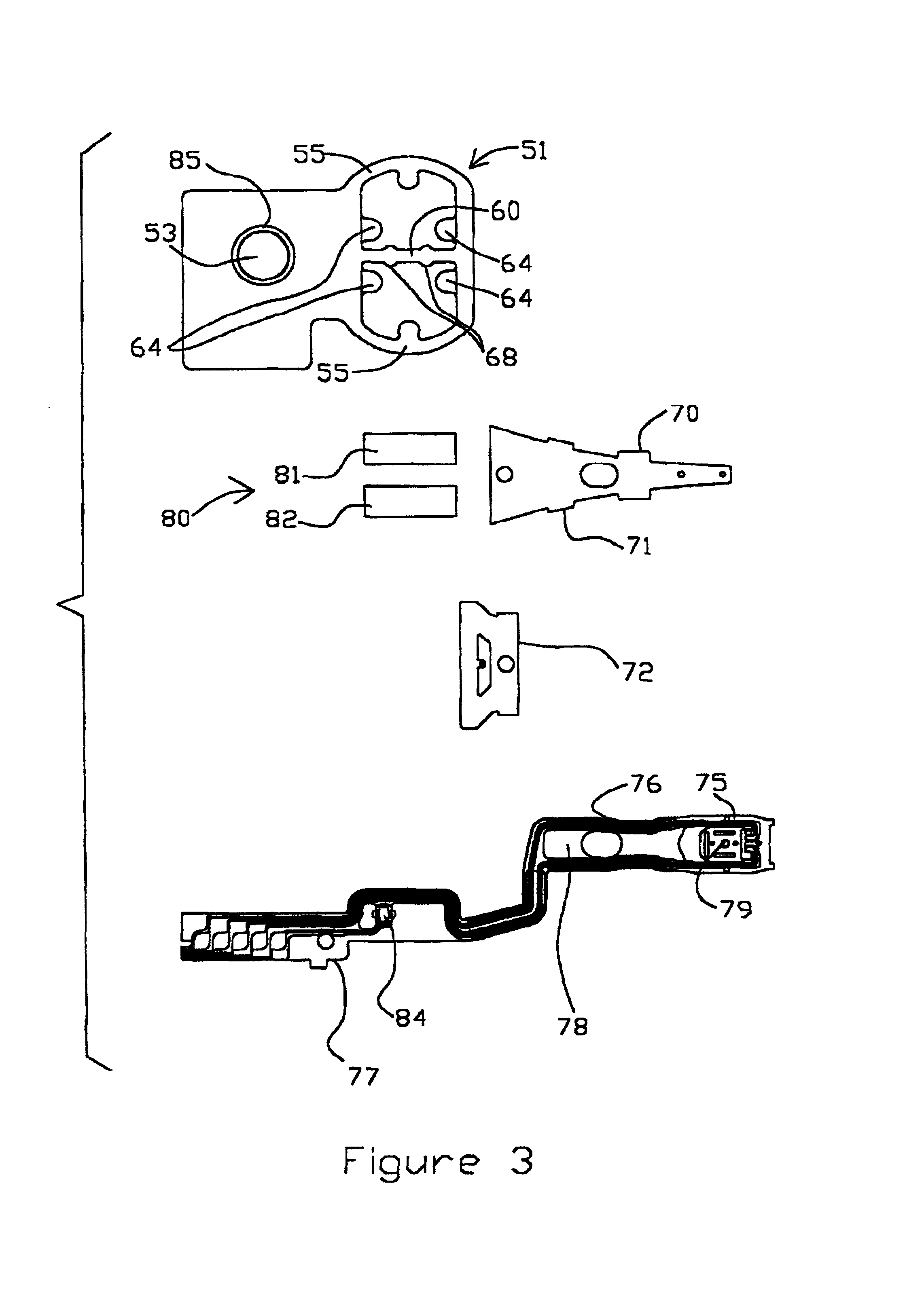
[0033]With reference to the attached Figures, it is to be understood that like components are labeled with like numerals throughout the several Figures. Referring now to FIGS. 1 to 7, a head suspension 50 in accordance with the present invention is shown, including a base plate 51, a load beam 70, a flexure 75 and a microactuator 80. The load beam 70 includes a rigid region 71 and a separate spring or radius region 72 that are fastened together, such as by welding or other suitable method as is known in the art. Numerous types of load beams 70, including both single piece and multiple piece configurations, are known in the art and are suitable for use on head suspensions 50 formed in accordance with the present invention. Alternatively, the base plate 51 and load beam 70 may be formed as a unitary member, or the base plate 51 may be formed unitarily with the actuation mounting system. This latter configuration is referred to by the assignee, Hutchinson Technology Inc. (hereinafter “...
third embodiment
[0057]In a manner similar to that described in the third embodiment, the hinge portion 212 is mounted to the base plate 220, preferably on the back or bottom side. As a result, the tab pairs 216 and 217 provide mounting surfaces within apertures 228 for the microactuator motors 241, 242. The microactuator motors 241 and 242 are sized to mount on the pairs of tabs 216, 217, spanning the apertures 228. As a result, the microactuator motors 241, 242 are generally inset within the ring spring region 225 between the mounting region 221 and the connecting member 229. The microactuator motors 241, 242 are preferably attached to the base plate 220 at the tabs 216,217, using methods described herein. As described above, protrusions 231 on center spar 230 are a stop that allows for faster and easier positioning and placement of the microactuator motors 241, 242 on the base plate 220.
[0058]The microactuator motors 241, 242 are electrically connected to the head suspension 200 by wire stitching...
fourth embodiment
[0061]In this embodiment, the head suspension 250 includes a base plate 260 that is similar in configuration to base plate 220 of the prior embodiment. However, in this embodiment, the base plate 260 includes ring springs 265 that have slightly larger inner and outer radii, 266 and 267 respectively, a slightly smaller sector angle 268 and a slightly narrower width 269, than those shown and described in the In this embodiment, the inner radius 266 ranges from about 0.3 millimeters to about 3.0 millimeters; preferably from about 1.5 millimeters to about 2.5 millimeters. In one preferred embodiment, the inner radius 266 is about 1.96 millimeters. The outer radius 267 ranges from about 0.7 millimeters to about 4.0 millimeters; preferably from about 2.0 to about 3.0 millimeters. In one preferred embodiment, the outer radius 267 is about 2.36 millimeters.
[0062]The sector angle 268 ranges from about 30 degrees to about 170 degrees. Preferably, the sector angle 268 of each ring spring 165 ...
PUM
| Property | Measurement | Unit |
|---|---|---|
| arc angle | aaaaa | aaaaa |
| arc angle | aaaaa | aaaaa |
| radius | aaaaa | aaaaa |
Abstract
Description
Claims
Application Information