Label wrapper block assembly

Active Publication Date: 2007-02-20
BRADY WORLDWIDE INC
View PDF31 Cites 24 Cited by
  • Summary
  • Abstract
  • Description
  • Claims
  • Application Information

AI Technical Summary

Problems solved by technology

Namely, attempting to apply labels to wires, especially small diameter wires, is time consuming, is inaccurate in that it is difficult to place the labels in such a way that the labels are square and aligned on the wire, and is inefficient in that it is difficult to properly and evenly secure the entire label to the surface of the wire.
However, these systems are designed to be used with large diameter cylindrical objects such as cans or bottles a

Method used


Image

  • Label wrapper block assembly
  • Label wrapper block assembly
  • Label wrapper block assembly

Examples


Embodiment Construction

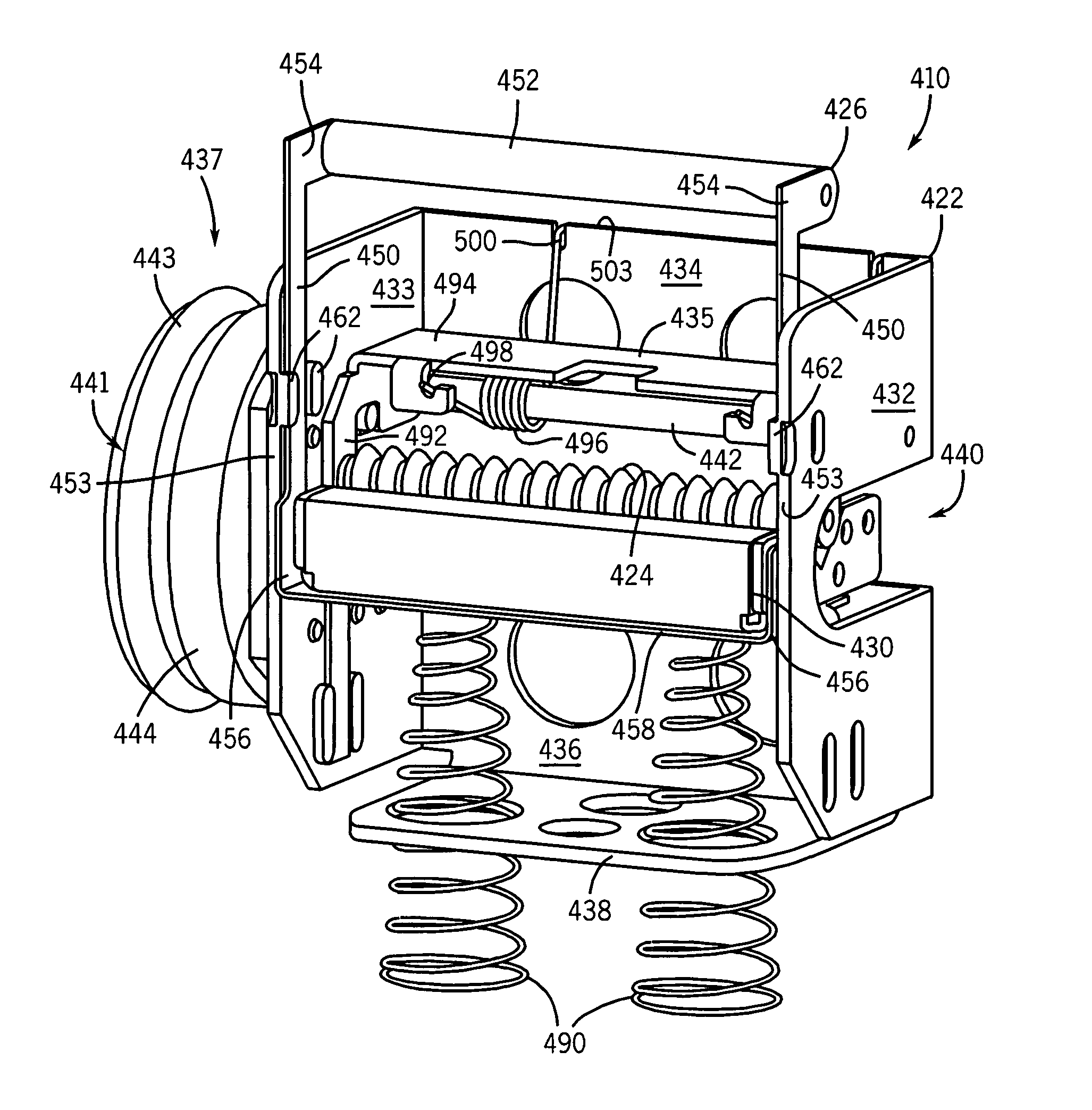
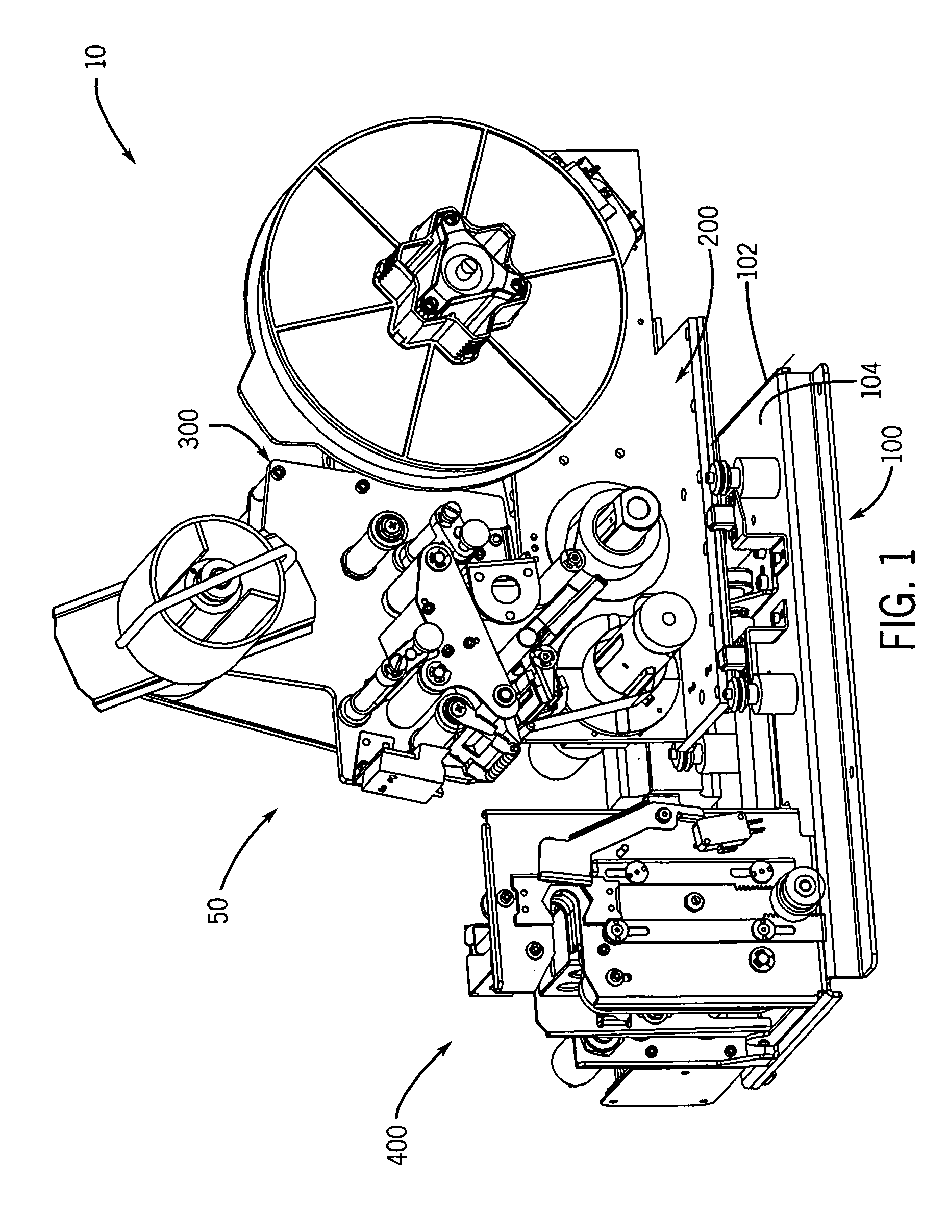
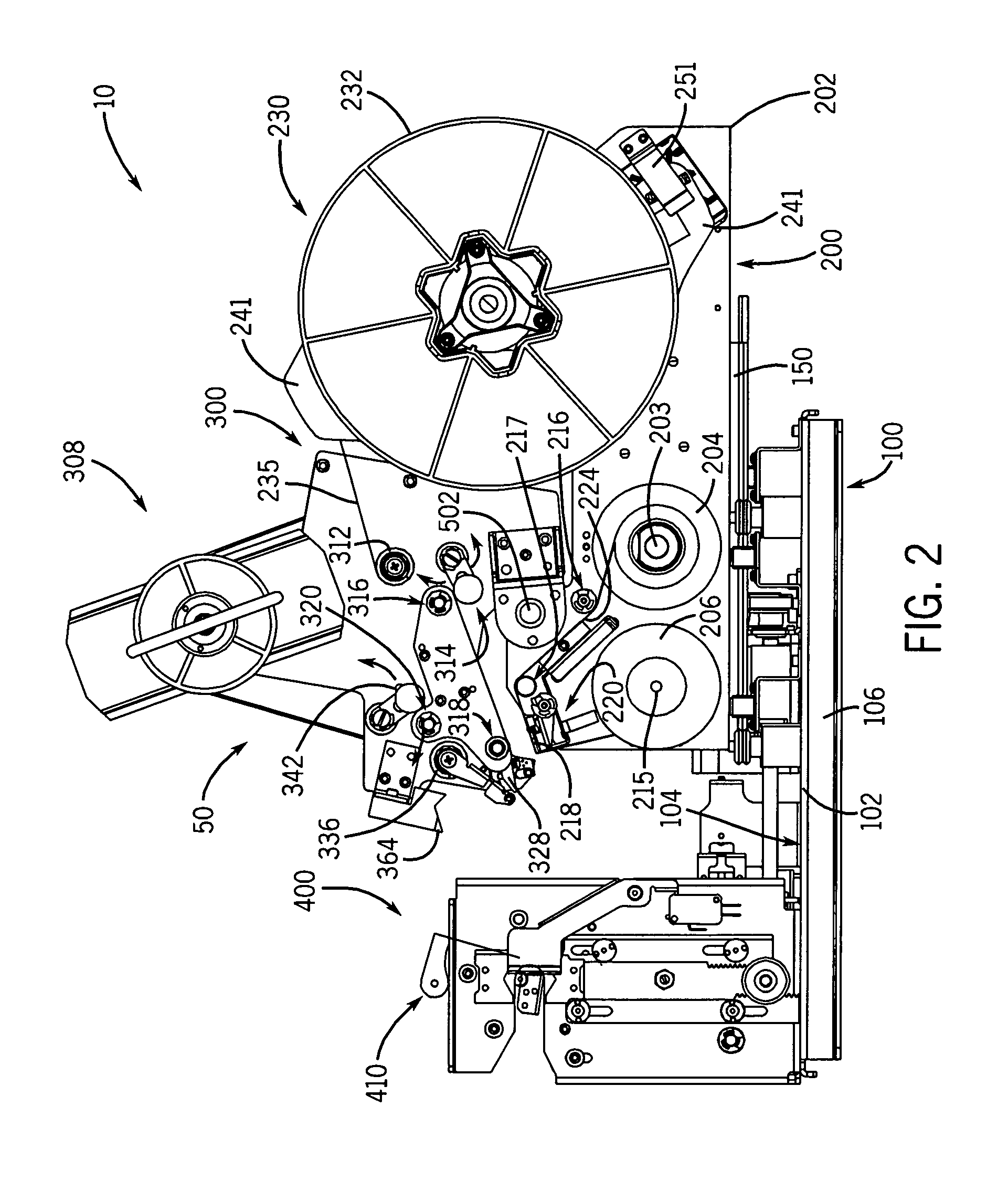
[0053]As shown in FIGS. 1–4, in one embodiment of the present invention a label applicator 10 includes a thermal transfer printer 50 and a label wrapper 400 mounted on a base assembly 100. A microprocessor electrically connected to both the printer 50 and label wrapper 400 integrates the operation of the printer 50 and label wrapper 400 to print a label and wrap the printed label onto a wire automatically. The microprocessor communicates with and controls the various motors of the apparatus through circuitry (not shown), which is discussed in more detail below.

Base Assembly

[0054]The base assembly 100 provides support and stability for the label applicator 10, and slidably mounts the printer 50 relative to the label wrapper 400, which is described in more detail below. As shown in FIGS. 5–8, in one embodiment of the invention the base assembly 100 includes a base 102 having a top wall 104 supported by a pair of longitudinal legs 106. Preferably, the top wall 104 and legs 106 are form...


PUM

PropertyMeasurementUnit
Flexibilityaaaaaaaaaa

Abstract

A label wrapper block assembly for mounting in a rotatably mounted wrapper frame in a label wrapper assembly includes a base having opposing ends joined by a top surface and a bottom surface. A channel extends between the ends in the top surface for receiving an object being wrapped by the label wrapper assembly. At least one biasing member is extendible into the channel for urging the label against the object received in the channel. In one embodiment, the at least one biasing member is a flexible material stretched across the base top surface.

Description

FIELD OF THE INVENTION[0001]The present invention relates to label wrappers, and more particularly to a label wrapper block assembly which applies a label to objects.BACKGROUND OF THE INVENTION[0002]Printers, such as thermal transfer label printers, are well known in the art for printing labels. In a typical thermal transfer label printer, a label and a thermal transfer printer ribbon are compressed between a print head and a roller and fed together past the print head. The print head produces sufficient heat in the appropriate locations to transfer the ink from the ribbon to the label to print a label.[0003]The labels produced by the printer are then applied to the wires being labeled by hand. Applying a label to a wire by hand has many drawbacks. Namely, attempting to apply labels to wires, especially small diameter wires, is time consuming, is inaccurate in that it is difficult to place the labels in such a way that the labels are square and aligned on the wire, and is inefficien...

Claims


Application Information

Patent Timeline
IPC IPC(8): B31F5/06B65C3/02B65C9/18B65C9/42B65C9/46
CPCB65C3/02B65C9/46B65C9/42B65C9/1865
Inventor SCHANKE, ROBERT L.BANDHOLZ, BRENT A.
Owner BRADY WORLDWIDE INC
Why Eureka
Try Eureka