Mammography unit positioning system and method

a positioning system and mammography technology, applied in mammography, medical science, diagnostics, etc., can solve the problems of variable quality of results, unpredictable quality, and difficult preparation of x-ray pictures of female breasts, and achieve the effect of less stress on patients and increased comfort for patients

Inactive Publication Date: 2007-02-20
ANLOGIC CORP (US)
View PDF9 Cites 7 Cited by
  • Summary
  • Abstract
  • Description
  • Claims
  • Application Information

AI Technical Summary

Benefits of technology

[0010]Among other features and advantages, the new and improved system and method of the present disclosure allows a mammography unit to be vertically raised and lowered, rotated, and tilted in preparation for a mammography examination. In addition, the new and improved system and method allows an X-ray tube and a film receptor of the mammography unit to be independently rotated, so that the X-ray tube and the film receptor can be even more precisely positioned with respect to a patient during a mammography examination. By enabling independent rotation of the x-ray tube and the compressor-Bucky assembly, the system provides increased comfort to the patient, and allows more breast tissue to be examined in a manner less stressful to the patient.

Problems solved by technology

X-ray photography of the female breast constitutes one branch of the broader field relating to diagnostic X-ray photography of soft tissues, but the preparation of X-ray pictures of the female breast is very difficult, particularly in that the correct adjustment and focusing of the system is rather complicated.
Moreover, the problems of focusing and adjustment were so difficult that the quality of the results was variable and rather unpredictable.

Method used


Image

  • Mammography unit positioning system and method
  • Mammography unit positioning system and method
  • Mammography unit positioning system and method

Examples


Embodiment Construction

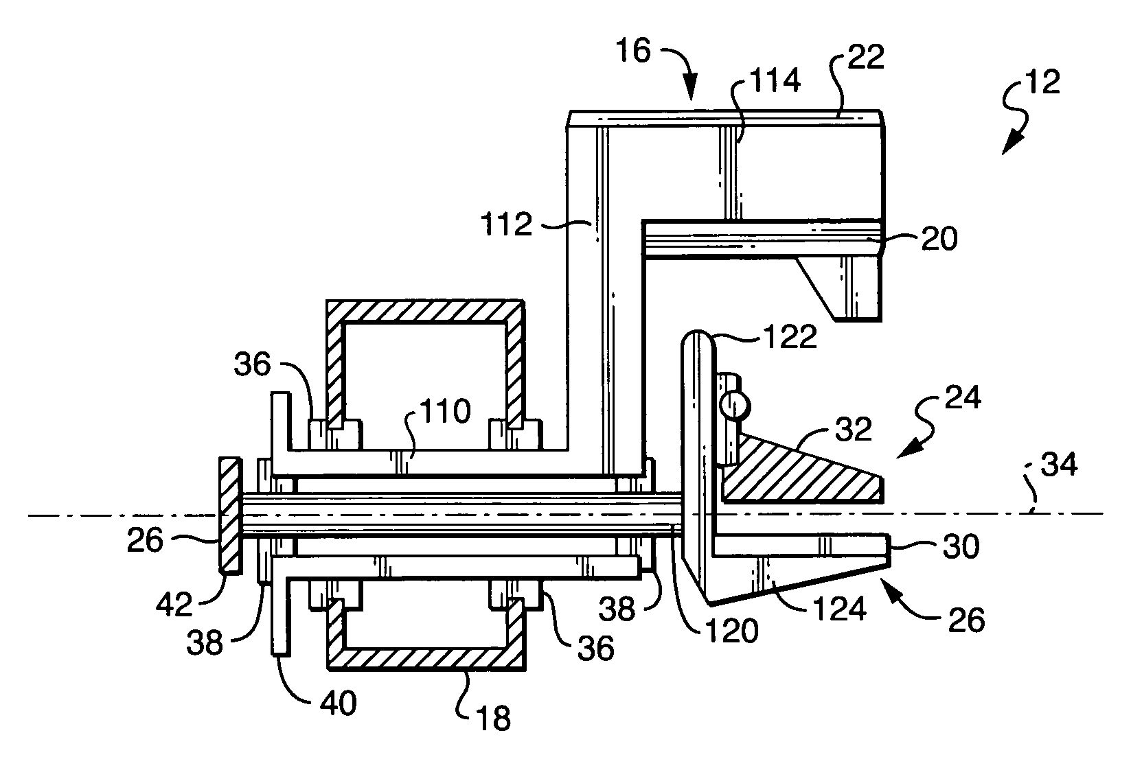
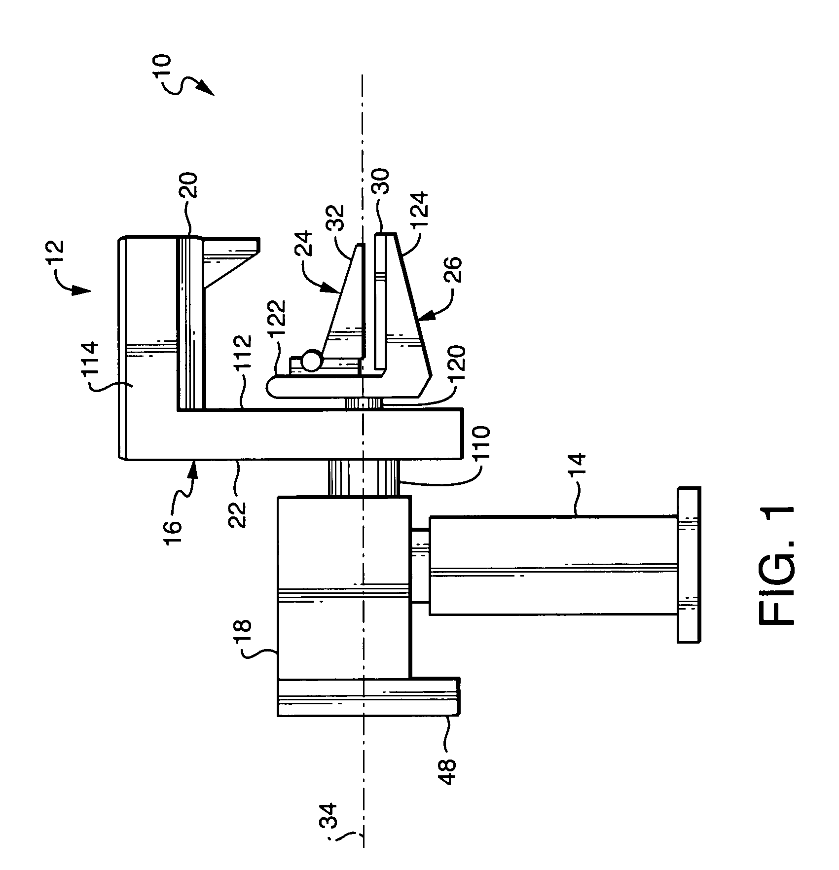
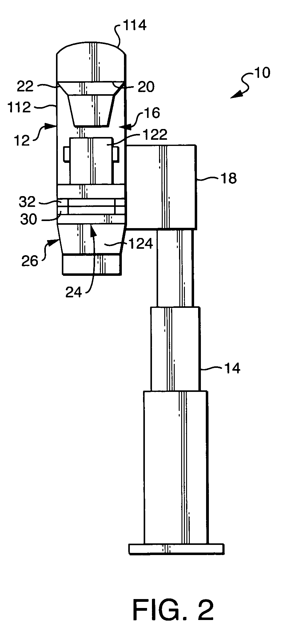
[0020]Referring to FIGS. 1 through 4, an exemplary embodiment of an x-ray mammography system 10 constructed in accordance with the present disclosure is shown. The x-ray mammography system 10 includes a mammography unit 12 supported on a vertical support stand 14. The mammography unit 12 includes a C-arm 16 connected to the support stand 14 via a casement 18, an x-ray tube 20 mounted on a first portion 22 of the C-arm 16, and a compressor-Bucky assembly 24 mounted on a second portion 26 of the C-arm 16 so that it is opposite the x-ray tube 20.

[0021]The compressor-Bucky assembly 24 includes a film receptor 30 (preferably a Bucky grid) and a plate-like compressor 32. The compressor 32 is movable with respect to the film receptor 30 such that a woman's breast may be positioned and compressed between the compressor 32 and the film receptor 30 during a mammography examination.

[0022]The first and the second portions 22, 26 of the C-arm 16 are arranged so that the x-ray tube 20 and the com...


PUM


Abstract

A system for positioning a mammography unit includes a C-arm, an x-ray tube mounted at one end of the C-arm, and a compressor-Bucky assembly mounted at an opposite end of the C-arm. The compressor-Bucky assembly includes a film receptor (preferably a Bucky grid) and a plate-like compressor. The x-ray tube and the compressor-Bucky assembly can be rotated together with the C-arm about a center of rotation. In addition, the x-ray tube and the compressor-Bucky assembly can be rotated independently of one another within the C-arm.

Description

CROSS-REFERENCE TO RELATED APPLICATIONS[0001]The present application claims priority to co-pending provisional U.S. patent application Ser. No. 60 / 485,840, which was filed on Jul. 9, 2003, is assigned to the assignee of the present application, and is incorporated herein by reference.FIELD OF THE DISCLOSURE[0002]The present disclosure relates generally to X-ray systems and, more particularly, to a system and method for supporting and positioning a mammography unit, including an X-ray tube and a film receptor, with respect to a patient for a mammography examination.BACKGROUND OF THE DISCLOSURE[0003]Mammography is a specific type of imaging that uses a low-dose x-ray system and high-contrast, high-resolution film for examination of the breasts. Most medical experts agree that successful treatment of breast cancer often is linked to early diagnosis. Mammography plays a central part in early detection of breast cancers because it can show changes in the breast up to two years before a p...

Claims


Application Information

Patent Timeline
Patent Type & Authority Patents(United States)
IPC IPC(8): A61B6/04
CPCA61B6/502A61B6/0414
Inventor MCKENNA, GILBERT
Owner ANLOGIC CORP (US)
Why Eureka
Try Eureka