Adaptive power control of ink melt heaters for uniform ink melt rate

a technology of ink melt heater and power control, which is applied in the field of printing systems, can solve problems such as failure of the system

Inactive Publication Date: 2007-02-27
XEROX CORP
View PDF18 Cites 15 Cited by
  • Summary
  • Abstract
  • Description
  • Claims
  • Application Information

AI Technical Summary

Problems solved by technology

The object of the control strategy is to avoid the printing system running out of ink while trying to print, because such an event can be a catastrophic failure to the system.

Method used


Image

  • Adaptive power control of ink melt heaters for uniform ink melt rate
  • Adaptive power control of ink melt heaters for uniform ink melt rate
  • Adaptive power control of ink melt heaters for uniform ink melt rate

Examples


Embodiment Construction

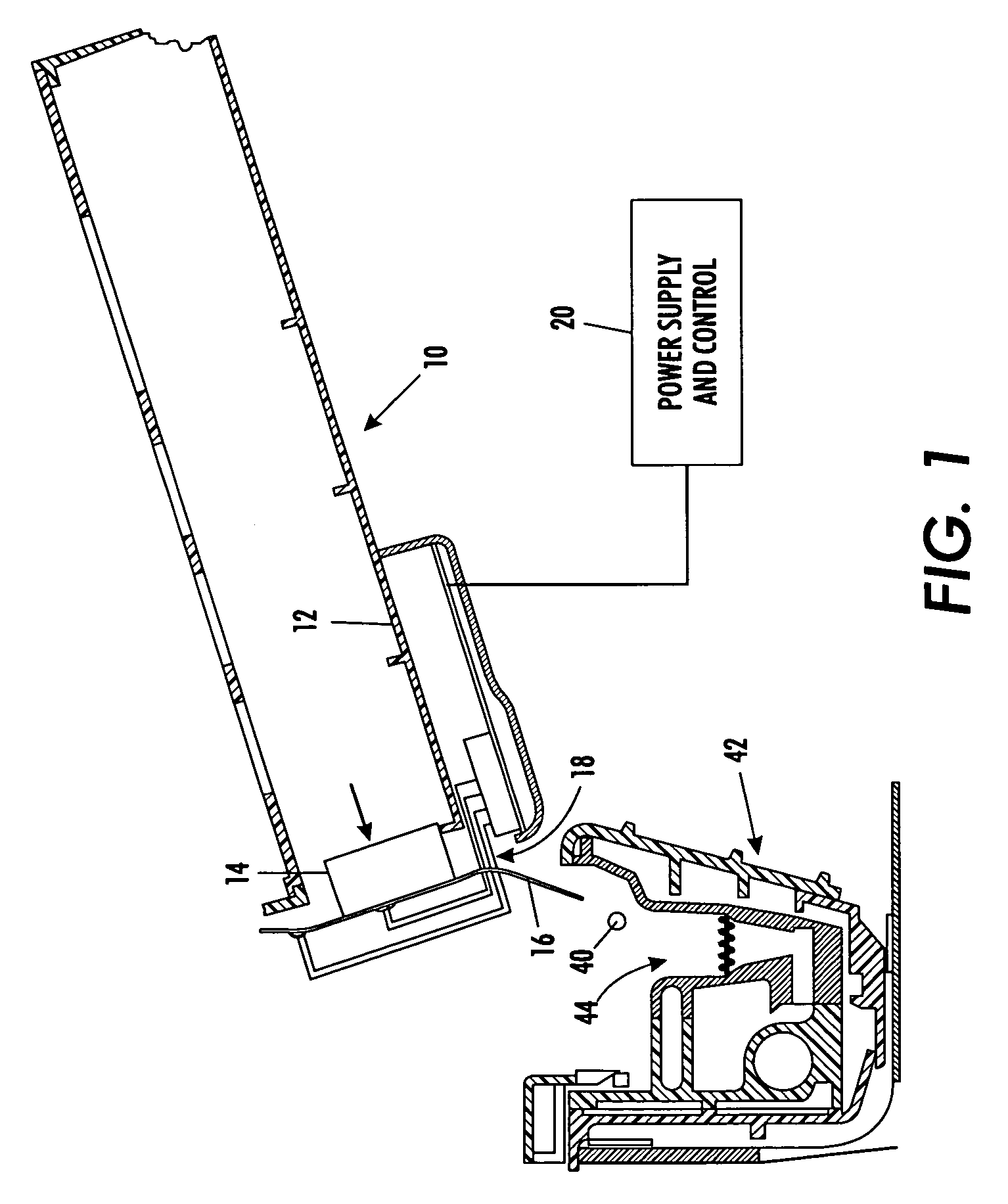
[0011]With reference to FIG. 1, the basic elements of an ink supply system in an ink “phase-changing” printing system can be seen. Ink loader assembly 10 includes a tray 12 for holding a solid phase ink stick 14. An ink melt heater 16 is disposed at an open end 18 of the tray to contact the ink stick and to allow for egress of liquid phase ink during heating from the tray 10. The heating plate 16 receives its heating energy from a power supply and control system 20. The heating element includes an assembly with resistance traces thereon so that electrical energy supplied thereto can be converted to heat energy.

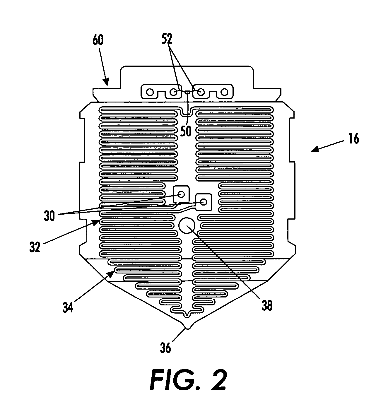
[0012]With particular reference to FIG. 2, power pads 30 connect wires (not shown) from the power supply to the heat plate 16. The plate includes a first portion 32 disposed to engage the ink stick and phase change the solid ink stick to a liquid. A heated liquid ink zone 34 then allows the liquid ink to flow to an ink drip point 36. It should be appreciated that the embodimen...


PUM


Abstract

A method and system for selectively controlling supplied power to an ink melt heater for maintaining a desired ink melt rate despite a varying ambient parameter affecting an actual melt rate. A predetermined amount of power is supplied to the ink melt heater intended to cause the desired ink melt rate. The ambient parameter is detected by the ink melt heater. A determination is made if the detected ambient parameter will cause a variance in the actual ink melt rate from the desired ink melt rate. If a variance is so determined, the supplied power is adjusted from the predetermined amount to an adjusted amount for realizing desired ink melt rate. The ambient parameter preferably comprises sensing a factor representative of at least one of local environmental air temperature to the printing system or adjacent ink temperature to the heat plate.

Description

BACKGROUND[0001]The present exemplary embodiments relate to printing systems and, in particular, printing devices which utilize a supply of colored inks to be communicated to a print head for document printing. More particularly, the present embodiments utilize solid ink sticks as the supply ink, which must be heated to a liquid form before being capable of communication to the print head. Such systems are commercially available under the PHASER® mark from Xerox Corporation.[0002]The present embodiments concern the structure, control system and operation methods of the heater element for causing a phase change in the solid ink supply to a liquid form capable of fluid communication to a print head for document printing.[0003]The basic operation of such phasing print systems comprises the melting of a solid ink stick, its communication to a reservoir for interim storage, and then a supply process from the reservoir to a print head for printing of a document. The object of the control ...

Claims


Application Information

Patent Timeline
Patent Type & Authority Patents(United States)
IPC IPC(8): B41J2/175G01D11/00
CPCB41J2/17593
Inventor GODIL, AMIN M.HINDMAN, LARRY E.
Owner XEROX CORP
Why Eureka
Try Eureka