PC board assembly

a technology of pc board and assembly, which is applied in the direction of coupling device connection, connection contact member material, coupling/disconnecting parts, etc., can solve the problem of less effective latching area of the rear portion of the electronic card, and limited movement distance of the distal end of the spring arm. , to achieve the effect of saving time and money and facilitating manufacturing

Inactive Publication Date: 2007-02-27
HON HAI PRECISION IND CO LTD
View PDF3 Cites 38 Cited by
  • Summary
  • Abstract
  • Description
  • Claims
  • Application Information

AI Technical Summary

Benefits of technology

[0008]Yet, during applying to different height applications between the electronic card and the printed circuit board, it may be required to change dimensions of only one of the latching device and the grounding device for complying with the different applications, thus saving time and money.
[0009]Another feature of the invention may optionally include the one-piece grounding device providing a plurality of grounding legs for compliance with the grounding pads on the printed circuit board so as to ease manufacturing.

Problems solved by technology

Because the positioning hole is so small that the positioning post is essentially compactly received therein, thus resulting in limited moving distance of the distal end of the spring arm.
As a result, the latching portion has less moveability and less effective latching area with regard to the rear portion of the electronic card.
Anyhow, the latching mechanism is made from a single metal piece in forming which results in complicated structure and the uncontrollable dimension and position precision.
Understandably, this design has difficulties in manufacturing.
On the other hand, the metallic latching mechanism disadvantageously tends to result in shorting if the neighboring component is densely arranged therearound.

Method used


Image

  • PC board assembly
  • PC board assembly
  • PC board assembly

Examples


Embodiment Construction

[0018]References will now be in detail to the preferred embodiments of the invention. While the present invention has been described in with reference to the specific embodiments, the description is illustrative of the invention and is not to be construed as limiting the invention. Various modifications to the present invention can be made to the preferred embodiments by those skilled in the art without departing from the true spirit and scope of the invention as defined by appended claims.

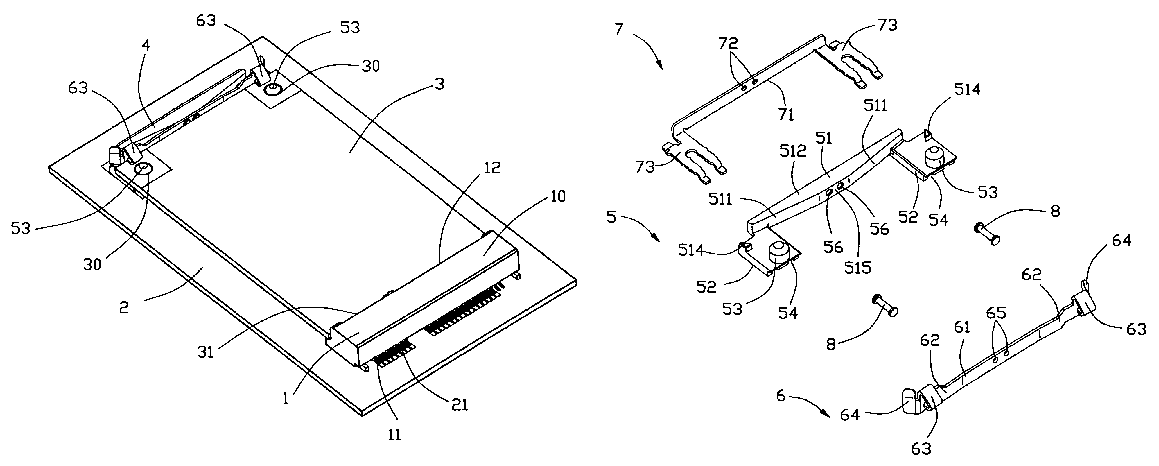
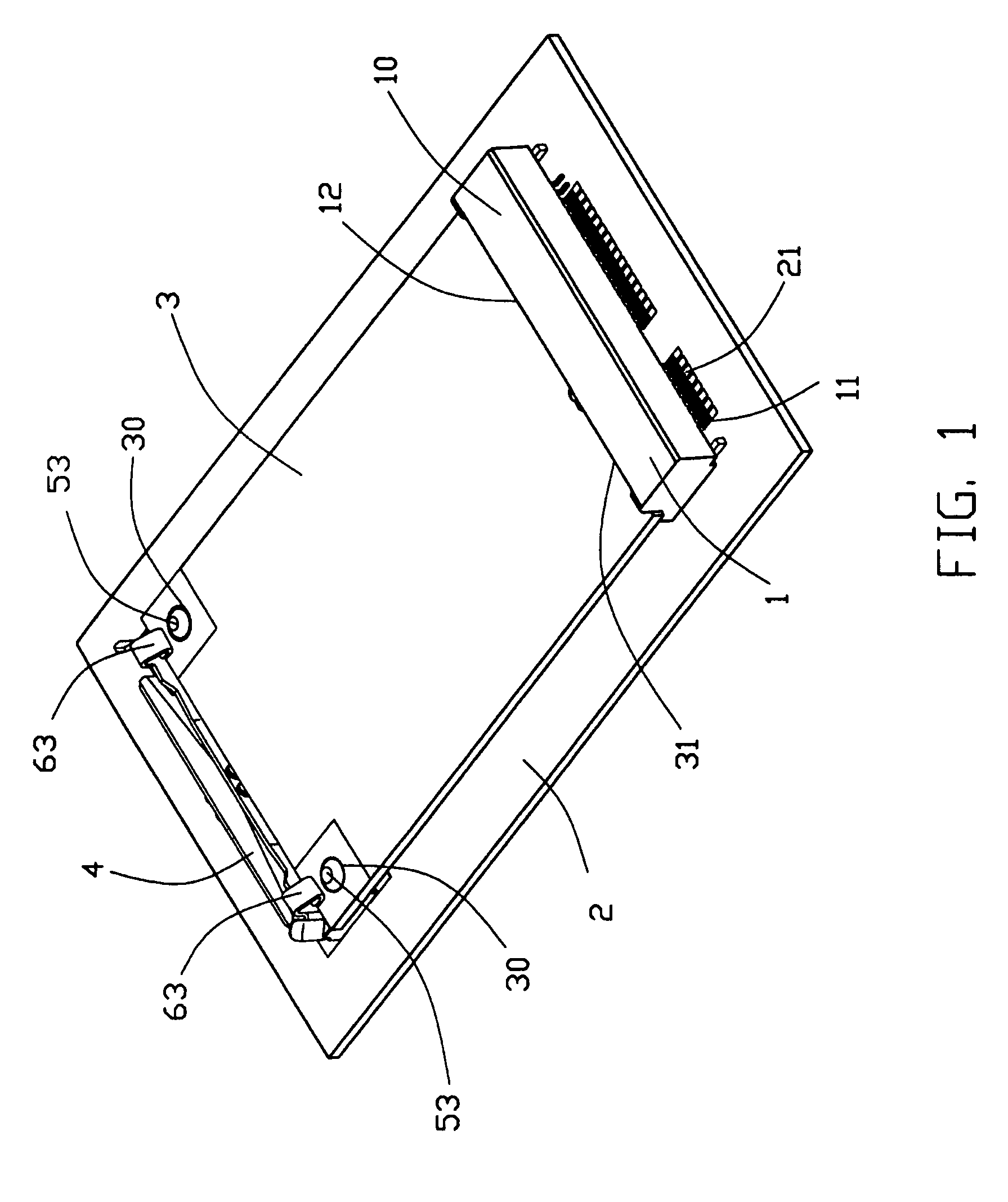
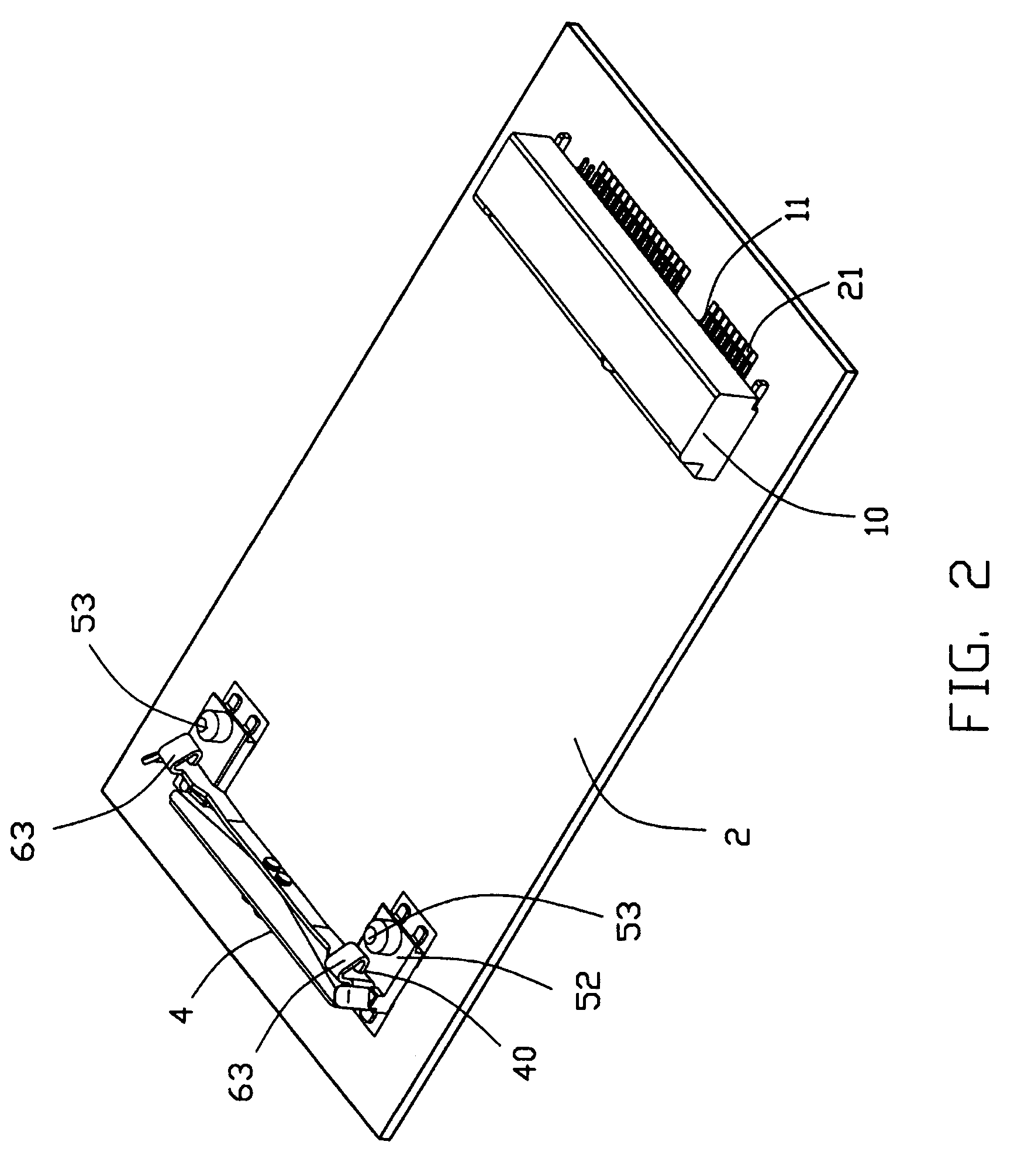
[0019]It will be noted here that for a better understanding, most of like components are designated by like reference numerals throughout the various figures in the embodiments. Referring to FIGS. 1–3, a latching mechanism 4 and a card edge connector 1 are commonly mounted to a printed circuit board 2 for holding an electronic card 3 on the printed circuit board 2.

[0020]One end of the printed circuit board 2 includes a plurality of conductive pads 21, and the other end thereof defines a pair of th...


PUM


Abstract

The latching mechanism includes an insulative fixing device, a metallic spring latching device and a metallic grounding device, wherein the fixing device includes the card supporting portion and a positioning post upwardly extending therefrom corresponding to the positioning hole of the electronic card. The latching device includes a connection portion connected to the fixing device, the spring arm extending from the connection portion and the hook portion located on the spring arm and extending toward the card edge connector for locking the rear portion of the electronic card. The grounding device is electrically connected to the latching device and includes mounting legs mechanically and electrically engaged with the corresponding grounding pads formed on the printed circuit board for grounding.

Description

BACKGAROUND[0001]1. Field of the Invention[0002]The invention relates to an electrical assembly, and particularly to a PC (Printed Circuit) board assembly having an electronic card electrically and mechanically connector to a mother board via an electrical connector and a latching mechanism in a parallel manner.[0003]2. The Related Art[0004]Taiwan patent number M261882 discloses a kind of latching mechanism for use with a card edge connector, wherein the latching mechanism including a spring piece including a fixed section and two spring arms, said fixed section being fixed to the printed circuit board and two spring arms extending from the two opposite ends of the fixed section, each of the spring arms including at a distal end a supporting portion and a latching portion, both of which defines positioning openings toward the card edge connector. The supporting portion defines the upward position post toward the card edge connector. The positioning openings confine the rear portion ...

Claims


Application Information

Patent Timeline
Patent Type & Authority Patents(United States)
IPC IPC(8): H01R13/62
CPCH05K7/1404H01R12/721H01R12/7005
Inventor CHOY, EDMONDXIAO, FENG
Owner HON HAI PRECISION IND CO LTD
Why Eureka
Try Eureka