Eureka AIR delivers breakthrough ideas for toughest innovation challenges, trusted by R&D personnel around the world.

Key structure

a key structure and key technology, applied in the field of key structures, can solve the problems of increasing manufacturing costs, increasing the complexity of the assembly process, etc., and the effect of reducing the total height of a manufactured produ

Active Publication Date: 2007-02-27
LITE ON IT TECH CORP +1
View PDF3 Cites 14 Cited by
  • Summary
  • Abstract
  • Description
  • Claims
  • Application Information

AI Technical Summary

Benefits of technology

[0013]The present invention provides a key structure having a scissor-like linkage structure that can reduce injection costs, reduce assembly costs, and lower the total height of a manufactured product. It applies single injection technology that form pivots directly in the pivotal holes of the scissor-like linkage structure. The present invention not only reduces the injection molding area, thereby reducing injection costs, but also avoids assembly steps completely. The present invention can save labor assembly costs, and avoid the possibility of product assembly failure.

Problems solved by technology

Especially concerning notebooks, space is limited and the keyboard structure is particularly important.
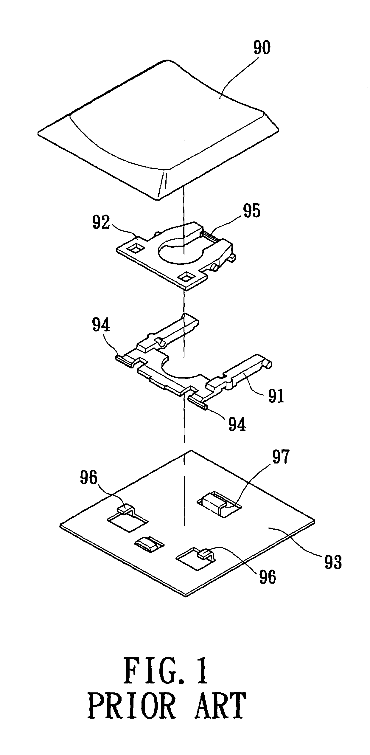
Therefore, the necessary area for forming the scissors-like linkage structure is relatively large, resulting in an increase in manufacturing costs and the complication of the assembly of the inner and outer arms.
Therefore, the assembly process is relatively complicated and time-consuming, which induces the high assembly costs.
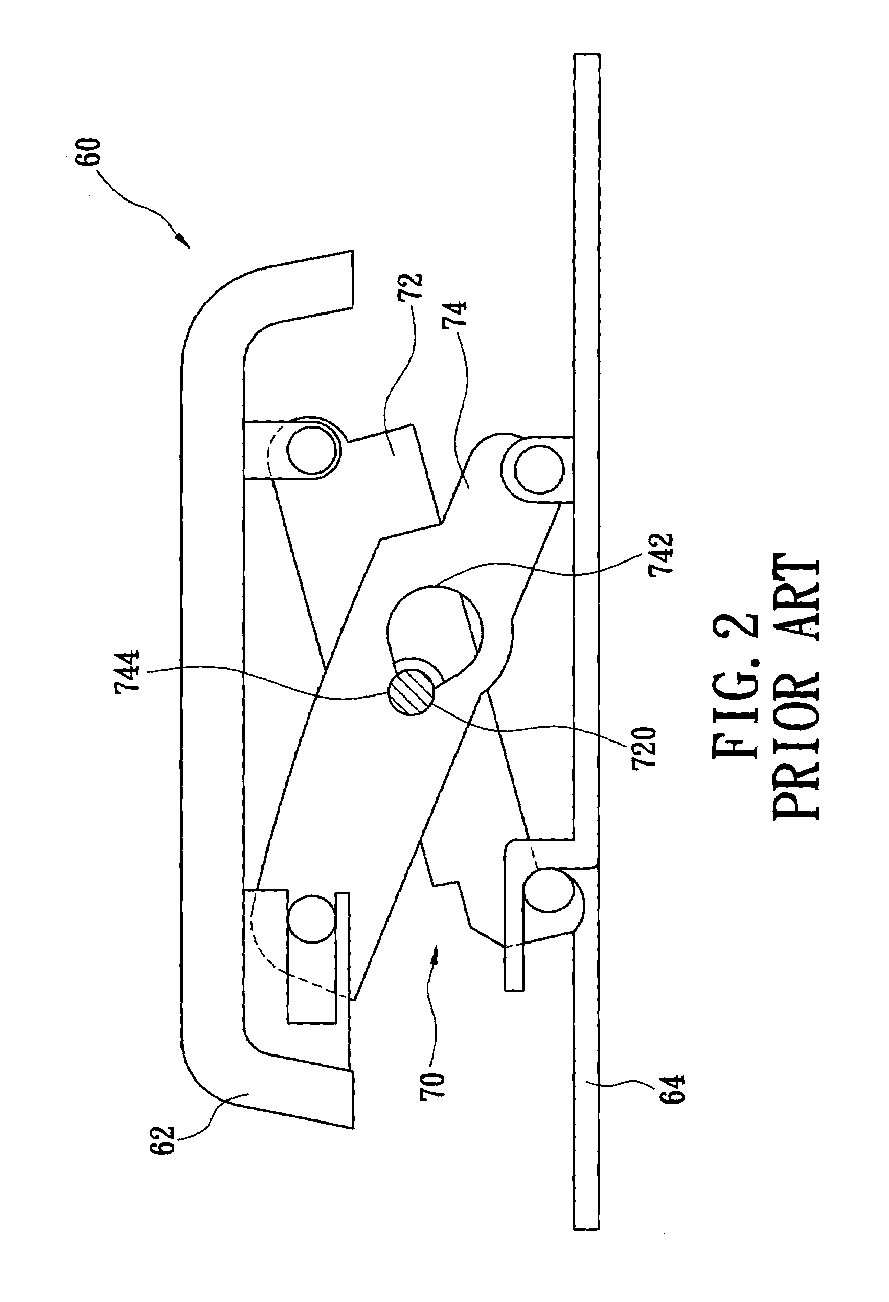
However, unavoidably, the scissors-like linkage structure of this prior art still needs one labor assembly step, which is pushing the pivots 720 of the first frame 72 into the second holes 744 of the second frame 74.
Such step not only raises labor costs, but also increases the possibility of damage caused by improper assembly.
It is therefore poorly designed for notebook computer keyboards.
The lateral force may cause the pivots 720 to break and raises the possibility of the product breaking down.

Method used


Image

  • Key structure
  • Key structure
  • Key structure

Examples


Embodiment Construction

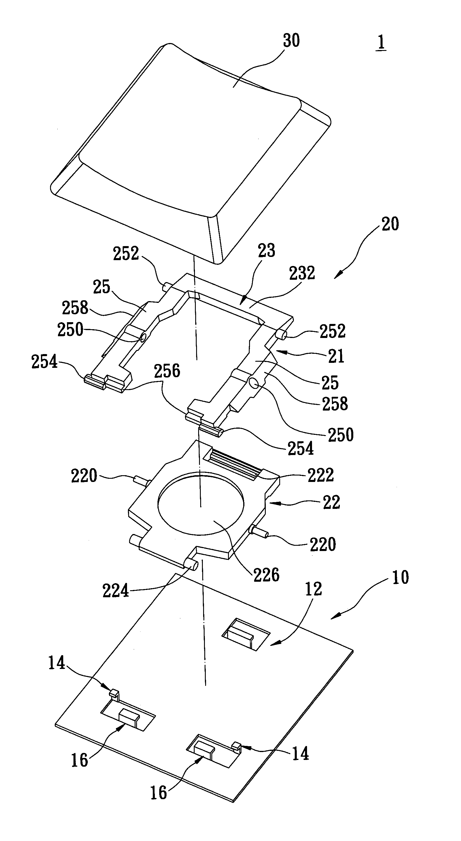
[0024]Please refer to FIG. 4, which illustrates an exploded perspective view of a key structure of the preferred embodiment according to the present invention. The present invention provides a key structure 1 comprising a base 10, a support member 20 and a key cap 30. The support member 20 is removably connected with the base 10. The key cap 30 is mounted above the support member 20 and connected to the support member.

[0025]The base 10 is formed with a front hook 12 and two rear hooks 14 for connecting pivotally with the support member 20.

[0026]Please refer to FIGS. 5 and 6, which respectively illustrate a top view and a side view of a support member of the key structure according to the present invention. The support member 20 comprises a first frame 21 and a second frame 22, which are formed by integral injection and are incorporated together during manufacturing procedure. In other words, there is no need to manufacture the first frame 21 and the second frame 22 separately and to...


PUM


Abstract

A key structure has a support member that reduces manufacturing costs, assembly costs, and the total height of the manufactured product. The support member is mounted between a base and a key cap. The support member has a first frame and a second frame, which are both formed in a united manner by injection. The first frame has a base portion and a pair of side arms connected with the base. The side arms both have a penetrated transverse pivotal hole formed therein. The second frame is disposed between the side arms and has a pair of pivots protruded respectively from two sides thereof. The pivots are formed and mounted directly in the pivotal holes during ejection molding, and an annular channel is formed for receiving a tubular mold during ejection molding.

Description

BACKGROUND OF THE INVENTION[0001]1. Field of the Invention[0002]The present invention relates to a key structure, particularly to a key structure having a scissor-like linkage structure which is adapted for an electronic product with keys, such as a notebook computer, a computer keyboard, a telephone, a printer or a multi-function printer, for controlling key strokes.[0003]2. Description of the Prior Art[0004]Keyboards are widely used with various devices, such as computers, and notebooks, to input characters and numerals. Especially concerning notebooks, space is limited and the keyboard structure is particularly important. To make a key on the keyboard easy to depress, the key is usually designed with a scissors-like linkage structure (often called a support member) to function no matter where force is exerted on the key cap. In other words, even though the force is exerted on the edge of the key cap, the force is generally equally distributed over the entire surface of the key ca...

Claims


Application Information

Patent Timeline
Patent Type & Authority Patents(United States)
IPC IPC(8): H01H9/26H01H3/12H01H13/70
CPCH01H3/125
Inventor LEE, TONG-SHUEHCHUANG, SHANG-CHIH
Owner LITE ON IT TECH CORP
Why Eureka
Eureka Blog
Learn More