Method for multi-link load balancing to improve sequenced delivery of frames at peer end

a load balancing and sequence delivery technology, applied in the field of data transmission, can solve problems such as frame relay users beginning to experience bandwidth limitation, frame relay users not trying to correct errors, and wan bandwidth not keeping pa

Inactive Publication Date: 2007-02-27
CISCO TECH INC OF CALIFORNIA
View PDF65 Cites 38 Cited by
  • Summary
  • Abstract
  • Description
  • Claims
  • Application Information

AI Technical Summary

Problems solved by technology

Frame relay does not attempt to correct errors.
While the number of applications running over networks has grown, the WAN bandwidth has not kept pace.
As network traffic increases, frame relay users begin to experience bandwidth limitation.
Eventually, the bandwidth in the connection runs out and workflow and productivity are seriously impacted.
Although the round robin approach is simple and easy to implement, it is not efficient because it does not take into consideration a possibility where the different links in the link bundle have different link speed.
When that is the case, the faster link is often underutilized.

Method used


Image

  • Method for multi-link load balancing to improve sequenced delivery of frames at peer end
  • Method for multi-link load balancing to improve sequenced delivery of frames at peer end
  • Method for multi-link load balancing to improve sequenced delivery of frames at peer end

Examples


Embodiment Construction

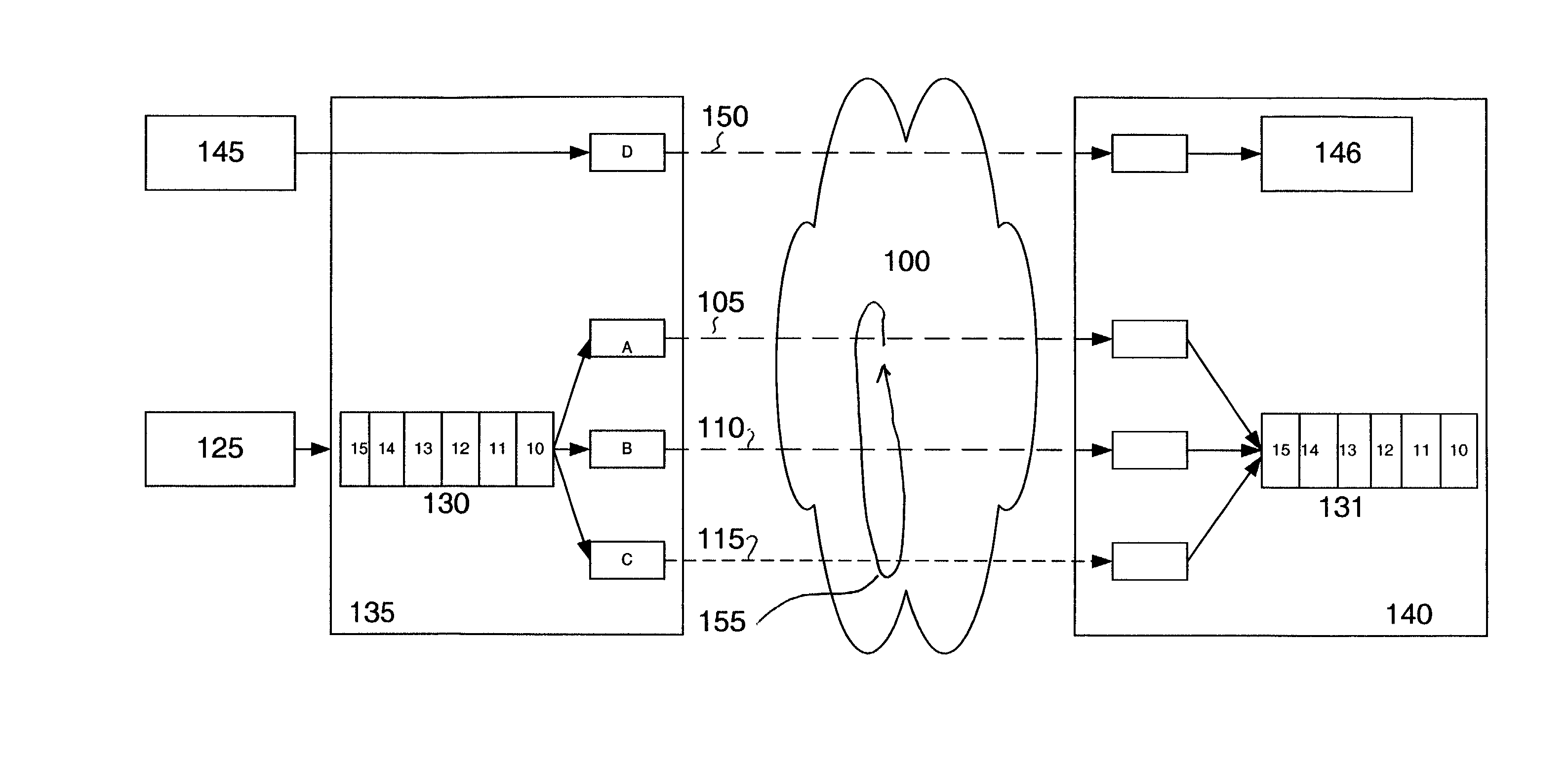
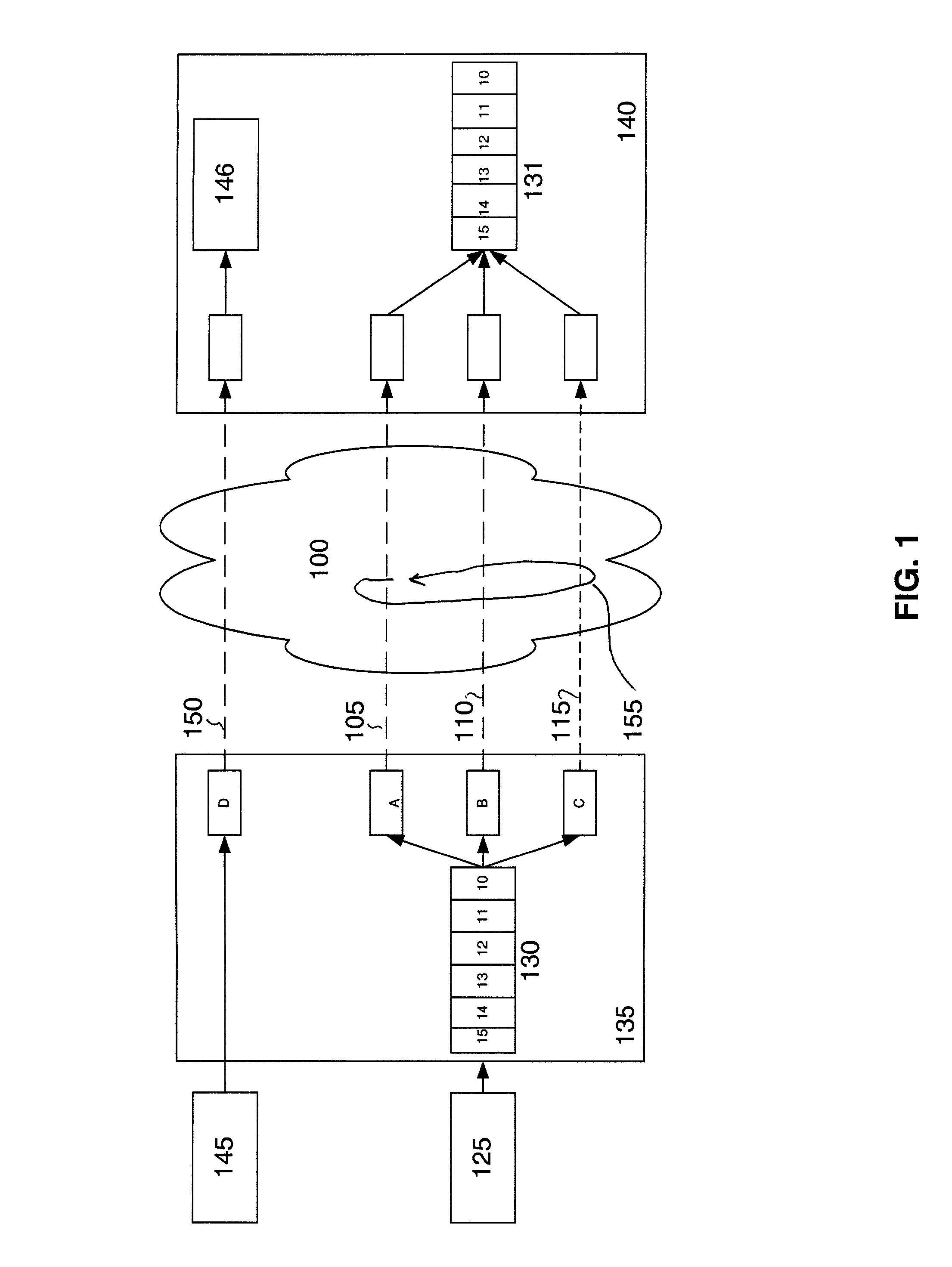
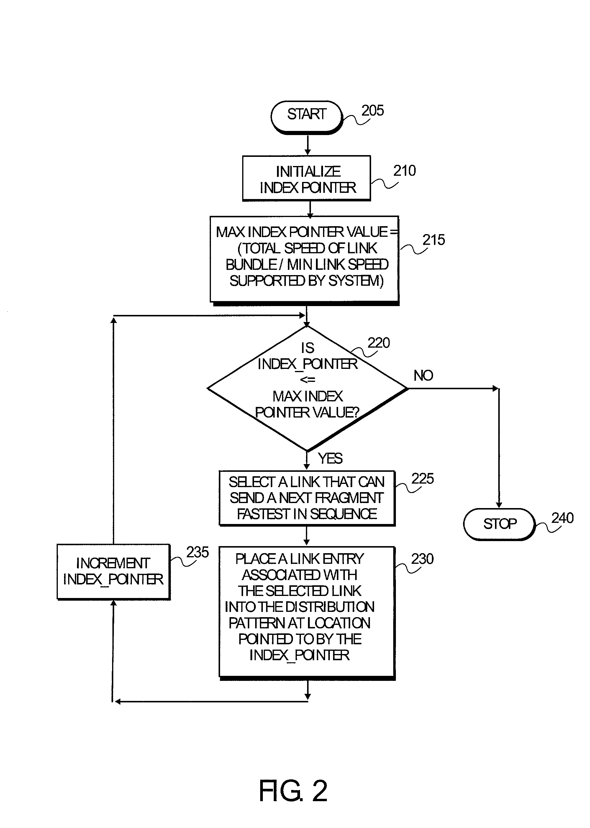
[0014]A method and a system for distributing Multilink Frame Relay (MFR) fragments are disclosed. A link distribution pattern is established based on a total speed of the links in a link bundle and a minimum possible link speed that is supported by a system. A link is selected when it is capable of transmitting a fragment in a shortest time while decreasing out-of-sequence arrival. A faster link in the link bundle may appear in the distribution pattern more than once. Each fragment is distributed to a link in the link bundle based on the distribution pattern.

[0015]FIG. 1 is an illustration of an end-to-end data transmission using MFR. The data processing engine (DPE) 135 and DPE 140 have previously been configured to transmit and receive data respectively using MFR across network 100. In this example, 0.5 Mbps is a minimum possible link speed supported by the DPE 135. Frame relay frames coming into the DPE 135 are sent to the DPE 140 using parallel transmission paths on a frame-by-f...


PUM


Abstract

A distribution pattern is established to distribute multilink frame relay (MFR) fragments. The distribution pattern includes a sequence of link entries associated with links in a link bundle. A number of link entries in the distribution pattern is determined by dividing a total link speed of the link bundle by a minimum possible link speed supported by a system. Each link entry is placed in the distribution pattern when the associated link is capable of transmitting a current fragment in a fastest transmit time. The fastest transmit time is determined based on the link speed of the link and a transmit time for the link to transmit other fragments previously allocated to that link. The fragments are distributed to the links in the link bundle according to the distribution pattern from a first link entry to a last link entry in the distribution pattern. The distribution pattern is repeated after the last link entry.

Description

FIELD OF THE INVENTION[0001]The present invention relates generally to field of data transmission. More specifically, the present invention relates to a method and an apparatus for delivering frame segments when using multilink frame relay (MFR).BACKGROUND[0002]Frame relay is a telecommunication service designed for data transmission for intermittent traffic between local area networks (LANs) and between end-points in a wide area network (WAN). Frame relay puts data into individually addressed variable-size unit called a frame. A frame size can be as small as a few bytes to as large as a few thousand bytes. The variable frame size means that frame transmit time and delay would be different for different frames. Frame relay does not attempt to correct errors. When an error is detected in a frame, it is simply dropped. The end points are responsible for detecting and retransmitting dropped frames. This speeds up overall data transmission. A Frame relay frame can incorporate packets fr...

Claims


Application Information

Patent Timeline
Patent Type & Authority Patents(United States)
IPC IPC(8): H04L12/46
CPCH04L47/10H04L47/16H04L47/125H04L47/43
Inventor SHARMA, ROHITAHN, CHANGSUNDARARAMAN, SWAMINATHAN
Owner CISCO TECH INC OF CALIFORNIA
Why Eureka
Try Eureka