Distributed control of data flow in a network switch

a network switch and data flow technology, applied in data switching networks, data switching multiplexes, instruments, etc., can solve the problems of large switching architectures, complex control algorithms and techniques, and inability to optimally use the bandwidth of synchronous cross-connects

Inactive Publication Date: 2006-02-28
FORCE10
View PDF14 Cites 46 Cited by
  • Summary
  • Abstract
  • Description
  • Claims
  • Application Information

AI Technical Summary

Problems solved by technology

However, because data flow between network nodes is not necessarily consistent, switching bandwidth may not be used optimally in a synchronous cross-connect.
A further disadvantage of synchronous switching architectures is that centralized switching control and interconnections grow exponentially as the input / output paths grow.
Therefore, large switching architectures are complex and require complex control algorithms and techniques.

Method used


Image

  • Distributed control of data flow in a network switch
  • Distributed control of data flow in a network switch
  • Distributed control of data flow in a network switch

Examples


Embodiment Construction

[0012]Techniques for distributed control of data flow in a network switch are described. In the following description, for purposes of explanation, numerous specific details are set forth in order to provide a thorough understanding of the invention. It will be apparent, however, to one skilled in the art that the invention can be practiced without these specific details. In other instances, structures and devices are shown in block diagram form in order to avoid obscuring the invention.

[0013]Reference in the specification to “one embodiment” or “an embodiment” means that a particular feature, structure, or characteristic described in connection with the embodiment is included in at least one embodiment of the invention. The appearances of the phrase “in one embodiment” in various places in the specification are not necessarily all referring to the same embodiment.

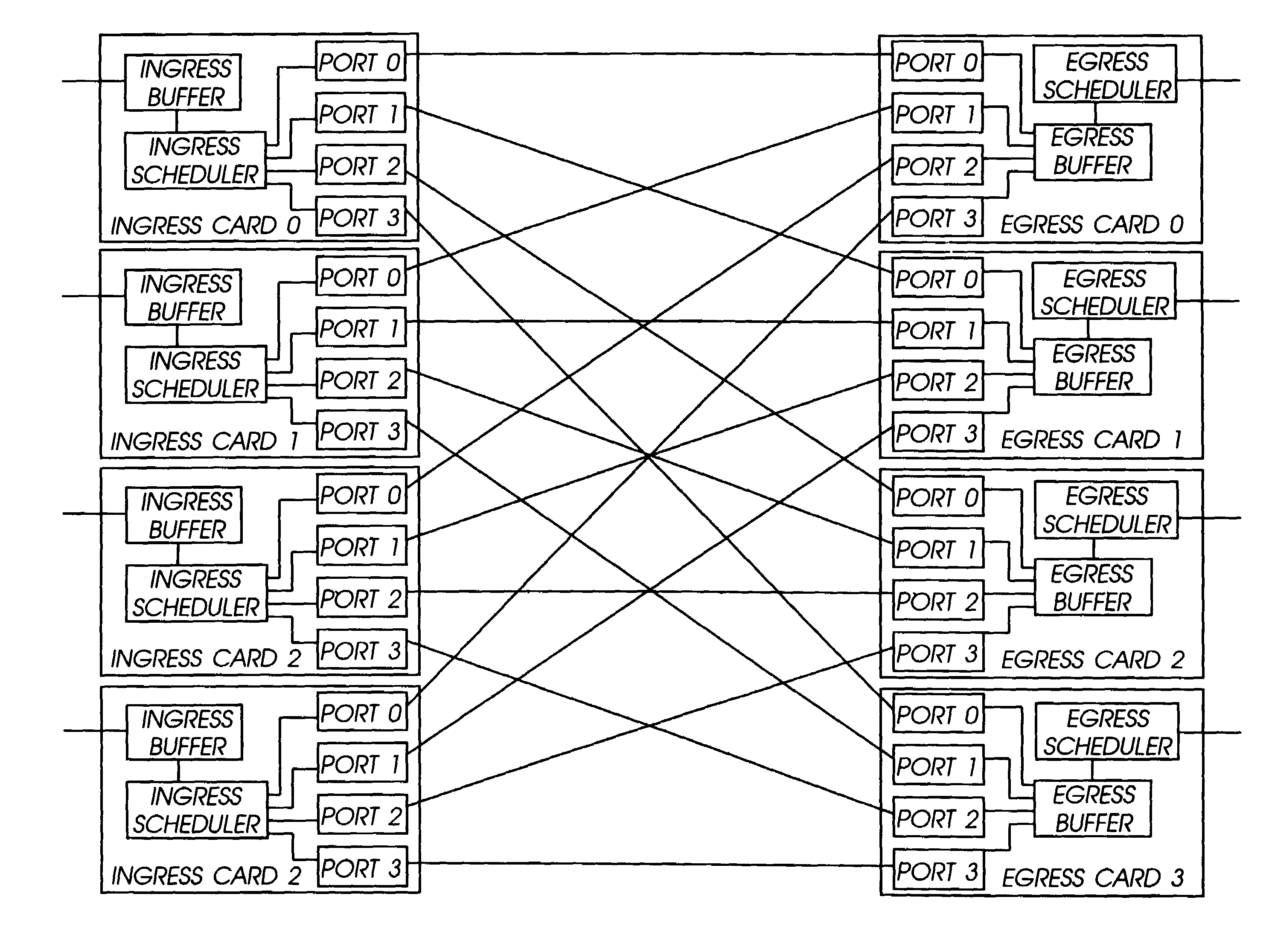
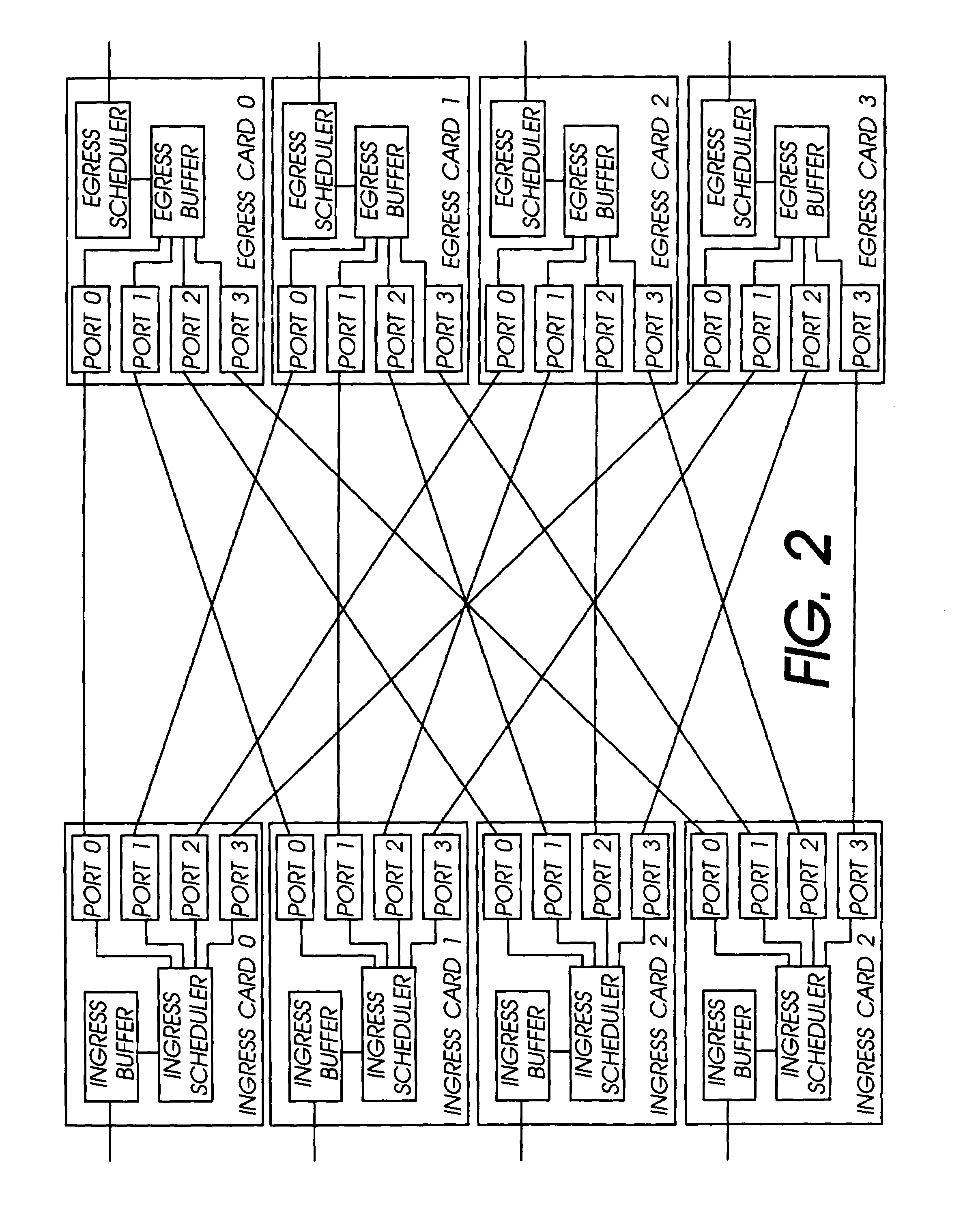
[0014]The network switch described herein provides a cell / packet switching architecture that switches between line inter...


PUM


Abstract

The network switch described herein provides a cell / packet switching architecture that switches between line interface cards across a meshed backplane. In one embodiment, the switching can be accomplished at, or near, line speed in a protocol independent manner. The protocol independent switching provides support for various applications including Asynchronous Transfer Mode (ATM) switching, Internet Protocol (IP) switching, Multiprotocol Label Switching (MPLS) switching, Ethernet switching and frame relay switching. The architecture allows the network switch to provision service on a per port basis. In one embodiment, the network switch provides a non-blocking topology with both input and output queuing and per flow queuing at both ingress and egress. Per flow flow-control can be provided between ingress and egress scheduling. Strict priority, round robin, weighted round robin and earliest deadline first scheduling can be provided.

Description

FIELD OF THE INVENTION[0001]The invention relates to network switches. More specifically, the invention relates to distributed control of data flow in network switches.BACKGROUND OF THE INVENTION[0002]In high bandwidth networks such as fiber optic networks, lower bandwidth services such as voice communications are aggregated and carried over a single fiber optic link. However, because the aggregated data can have different destinations some mechanism for switching the aggregated components is required. Switching can be performed at different levels of aggregation.[0003]Current switching is accomplished in a synchronous manner. Signals are routed to a cross-connect or similar switching device that switch and route signals at some predetermined granularity level, for example, byte by byte. Synchronous switching in a cross-connect is a logically straight forward method for switching. However, because data flow between network nodes is not necessarily consistent, switching bandwidth may...

Claims


Application Information

Patent Timeline
Patent Type & Authority Patents(United States)
IPC IPC(8): H04J3/14H04L12/56
CPCH04L12/5601H04L47/521H04L47/564H04L47/621H04L49/3018H04L49/3027H04L49/3081H04L49/405H04L49/606H04L49/90H04L49/9068H04L12/5693H04L2012/5679H04L49/10H04L49/20H04L2012/5651H04L47/50H04L49/112
Inventor WEST, STEVEBRANDIS, DIRKSMITH, RUSSMARRONE, FRANK
Owner FORCE10
Why Eureka
Try Eureka