Relay apparatus for encrypting and relaying a frame

a relay apparatus and frame technology, applied in the field of relay apparatus for realizing a secret communication, can solve the problems of unfavorable communication, unreliable communication, and unreliable transmission, and achieve the effect of simple configuration

Inactive Publication Date: 2008-02-28
FUJITSU LTD
View PDF8 Cites 47 Cited by
  • Summary
  • Abstract
  • Description
  • Claims
  • Application Information

AI Technical Summary

Benefits of technology

[0022]Also, by using the cryptographic key based on the sequence number as mentioned above, there is no longer a need for dynamically exchanging key information. It is also possible to generate the cryptographic key with a relatively simple configuration. Therefore, the encryption process and the decryption process degrade the relay speed of the entire relay apparatus to a smaller degree.

Problems solved by technology

Thus, when the communication is intercepted, important information is leaked out.
There are several methods, as described below, and all have problems.
(a) According to EtherIP, an EtherFrame can be transferred only to a specific destination, which results in the limitation to the one-to-one communication topology. That is, the method is only capable of encrypting the communication between a pair of switches having a one-to-one relationship. In a general office LAN (Local Area Network), however, N-to-N communication is often conducted.
(b) Since EtherIP does not perform a bridge operation, it does not learn a MAC address and cannot avoid unnecessary transfers, which generates unnecessary traffic.
(c) It uses a complicated protocol stack comprising IP, IPsec, and EtherIP. The protocol stack is complicated because it comprises these three protocols, IP requires routing, and IPsec requires key exchange. Since the protocol stack is complicated, the configuration definition is also complicated. Accordingly, communications equipment is not easy to operate and maintain.
(d) Since the protocol stack is complicated, realization as hardware is difficult. Meanwhile, realization as software results in a longer processing time. Therefore, it is difficult to realize a Gbps-class function.
The second method also has the same problems as the first method.
(e) The switch as the participant of the cryptographic communication needs to be identified, and the key needs to be exchanged with each participating switch using a key exchange protocol. Accordingly, it is not suitable for a topology in which a plurality of switches perform the encrypted communication in an N-to-N relationship since the process becomes too complicated.
(f) The granularity of encryption is in units of physical interfaces. That is, frames sent and received between two specific switches are either all encrypted or all not encrypted. Therefore, it cannot handle a smaller granularity to determine whether or not to perform the encryption for each VLAN (Virtual LAN).

Method used


Image

  • Relay apparatus for encrypting and relaying a frame
  • Relay apparatus for encrypting and relaying a frame
  • Relay apparatus for encrypting and relaying a frame

Examples


Embodiment Construction

[0038]The preferred embodiments of the present invention are described in detail below with reference to the drawings. For items that are essentially identical, the same numerals or numerals differing only in subscripts are assigned.

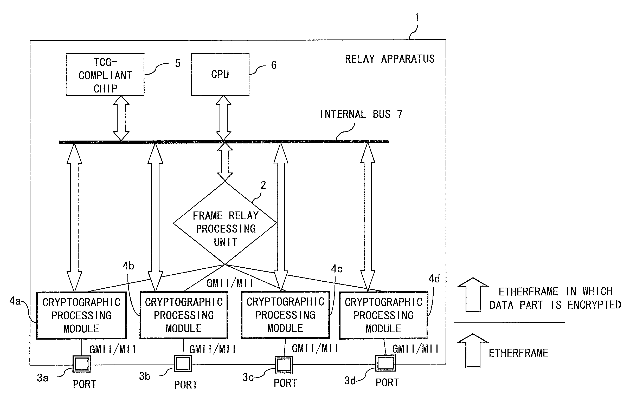
[0039]The frames sent and received in Layer 2 can be, for example, a MAC frame of DIX Ethernet or a MAC frame of IEEE802.3, which differ in their details but are almost identical in formats. The distinction is not important in the present invention. Therefore, the simple expression “frame” is used hereinafter as the generic term for those MAC frames.

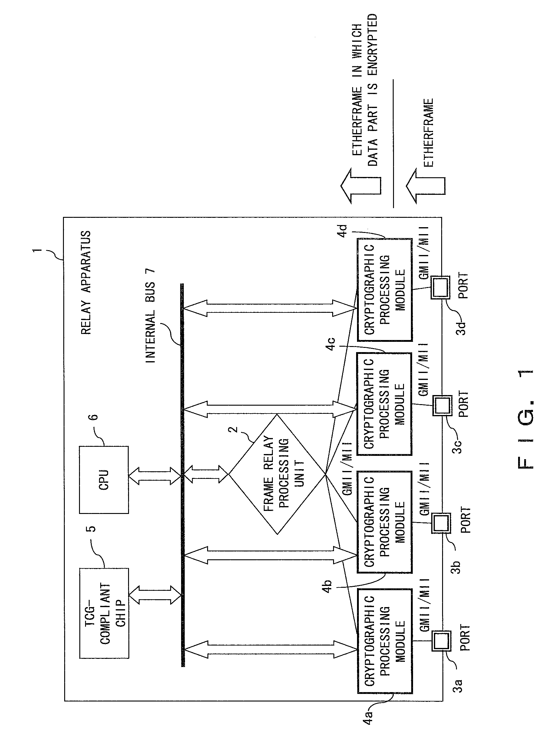
[0040]FIG. 1 is a block diagram of a relay apparatus according to an embodiment of the present invention. By utilizing the relay apparatus 1 in FIG. 1, a frame can be encrypted to realize a secret communication between the relay apparatuses (switches). The conventional Ethernet communication has a downside not only in that no encryption process is performed with the communication, but also that the Ethernet c...


PUM


Abstract

A relay apparatus comprises a frame relay processing unit for relaying a frame, a plurality of ports for sending and receiving the frame to and from the outside, and a cryptographic processing module corresponding to each of the ports. Each cryptographic processing module is connected to the corresponding port and to the frame relay processing unit by means of general-purpose interfaces such as MII. The cryptographic processing module performs the encryption process and decryption process so that the frame relay processing unit can concentrate on the relay process and the relay speed is not subject to degradation. Also, the cryptographic processing module can generate a different cryptographic key for each frame without requiring dynamic exchange of key information.

Description

BACKGROUND OF THE INVENTION[0001]1. Field of the Invention[0002]The present invention relates to an apparatus for realizing a secret communication by encrypting and relaying frames in the data link layer.[0003]2. Description of the Related Art[0004]Ethernet has been widely used for purposes ranging from personal use to corporate backbone systems because it realizes high-speed communications such as 10 Mbps, 100 Mbps, and 1 Gbps, and communications equipment such as NICs (Network Interface Cards), hubs, switches, and cables are affordable and easily available.[0005]The Ethernet standard defines the specifications of the physical layer (also referred to as Layer 1) and the data link layer (also referred to as Layer 2) in the OSI (Open Systems Interconnection) reference model. Layer 2 is further divided into two sublayers according to the IEEE (Institute of Electrical and Electronic Engineers) 802.3 standard in which Ethernet was standardized. The sublayer close to Layer 1 is the MAC (...

Claims


Application Information

Patent Timeline
Patent Type & Authority Applications(United States)
IPC IPC(8): H04L9/00G06F12/14H04L9/32G06F11/30H04L9/14H04L9/36H04L12/70H04L12/801H04L12/911
CPCH04L12/4641H04L12/4645H04L9/0869H04L63/0428H04L63/164H04L63/0272
Inventor IIDA, TAKAMITSUSAKURAI, HIDESHIOBARA, SATOSHINAKAJIMA, YUKIHIROSAKUMA, TAKAYUKI
Owner FUJITSU LTD
Why Eureka
Try Eureka