Automated lawn cutting and vacuum system

Inactive Publication Date: 2007-03-06
WILLIS II HULEN J
View PDF12 Cites 38 Cited by
  • Summary
  • Abstract
  • Description
  • Claims
  • Application Information

AI Technical Summary

Benefits of technology

[0005]The present invention is generally directed to an automated lawn cutting and vacuum system. The system includes an automated lawnmower typically having a storage bin for receiving grass clippings. A control panel provided on the mower housing automatically controls the mowing, driving and steering functions of

Problems solved by technology

Conventional push-type, self-propelled and riding lawnmowers suffer from the disadvantage of requiring an operator to maintain direct control over the

Method used


Image

  • Automated lawn cutting and vacuum system
  • Automated lawn cutting and vacuum system
  • Automated lawn cutting and vacuum system

Examples


Embodiment Construction

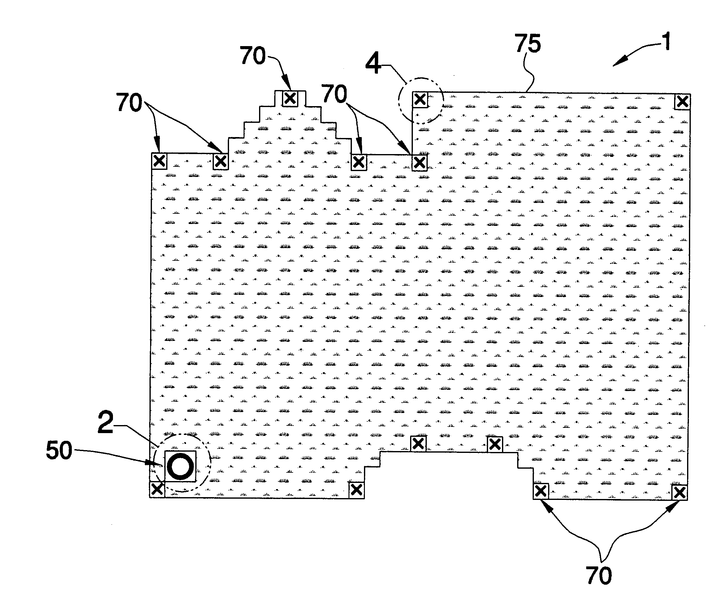
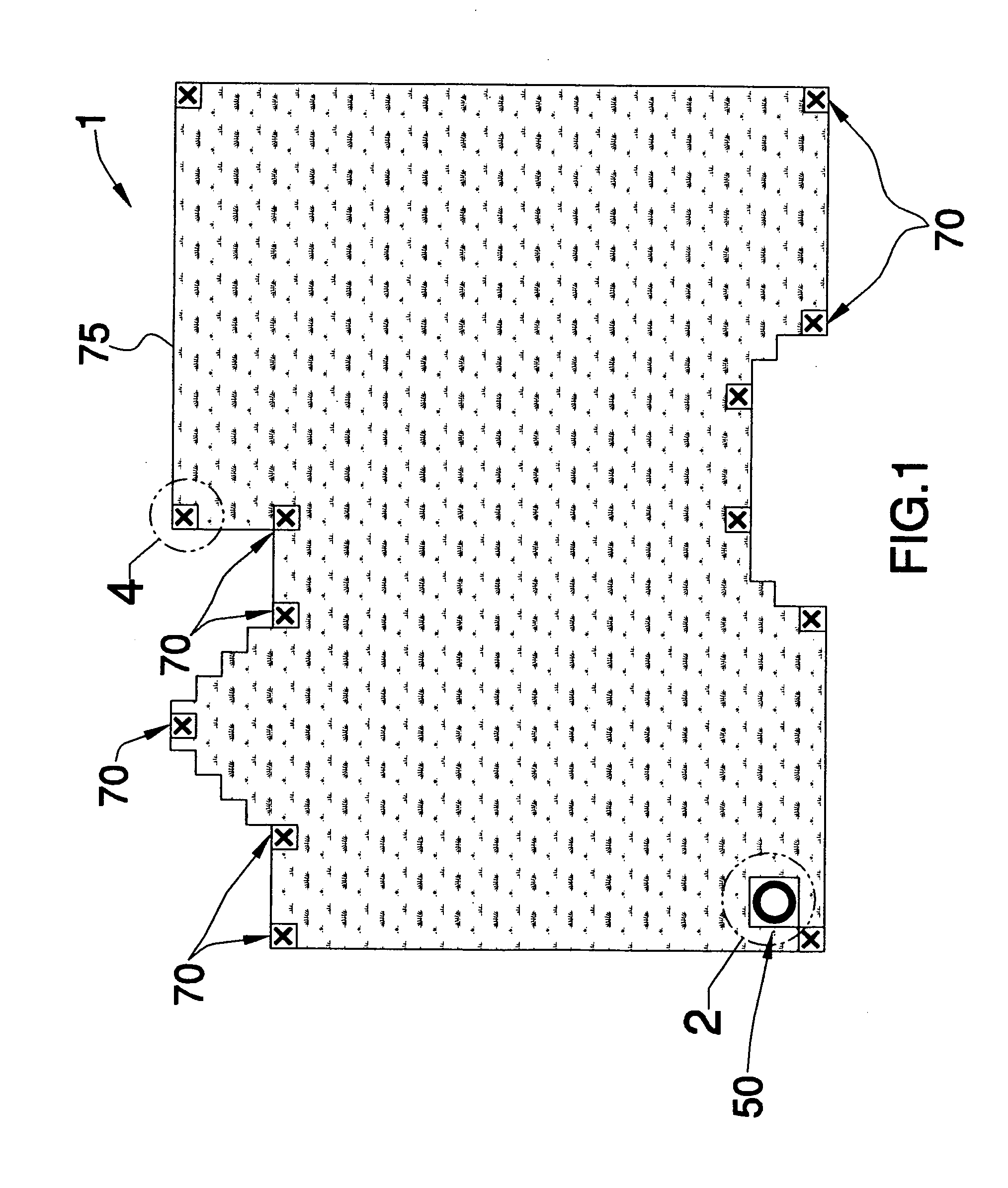
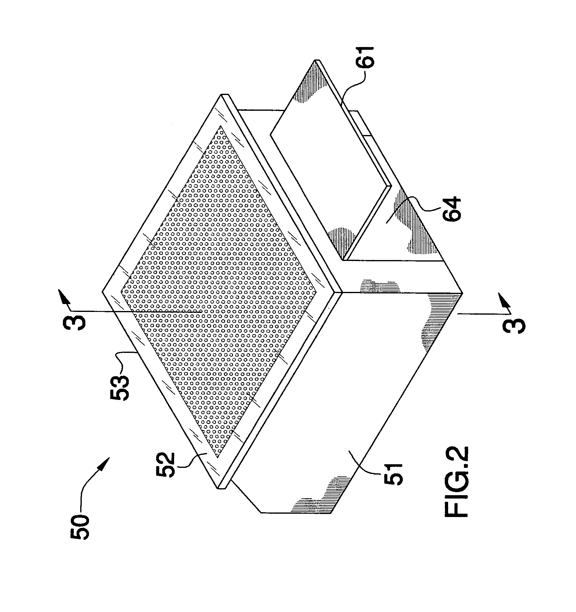
[0013]Referring to the drawings, an illustrative embodiment of the automated lawn cutting and vacuum system, hereinafter system, of the present invention is generally indicated by reference numeral 1 in FIGS. 1 and 3. Briefly, the system 1 includes an automated lawnmower 2 (FIG. 3) which is suitable for cutting grass on a lawn 75 (FIG. 1). Multiple perimeter sensors 70 are placed in spaced-apart relationship to each other around the perimeter of the lawn 75 to emit infrared beams and form a “virtual wall” which prevents the automated lawnmower 2 from straying beyond the edges of the lawn 75 in use as will be hereinafter described. The system 1 further includes a mower home base enclosure 50 in which the automated lawnmower 2 is stored and typically re-charged when not in use.

[0014]As illustrated in FIG. 6, the automated lawnmower 2 typically includes a mower housing 3 which may be configured in the shape of an automobile, as shown, or may be any desired alternative shape. The mower ...


PUM


Abstract

An automated lawn cutting and vacuum system is disclosed. The system includes an automated lawnmower comprising a mower housing. A control panel provided on the mower housing automatically controls the mowing, driving and steering functions of the automated lawnmower.

Description

FIELD OF THE INVENTION[0001]The present invention relates to lawnmowers and lawnmowing accessories. More particularly, the present invention relates to an automated lawn cutting and vacuum system having an automated lawnmower and a mower home base enclosure in which the lawnmower is kept when not in use for re-charging of the mower and in which grass clippings are removed from the mower.BACKGROUND OF THE INVENTION[0002]A variety of different types of lawnmowers are known in the art for mowing grass on residential and business lawns. One of the most common types of lawnmowers includes a gas-powered or electric-powered engine which is mounted on a mower housing and drives a blade or blades inside the mower housing. A mower handle extends from the mower housing to enable a user to push the mower on the lawn as the rotating blade cuts the grass.[0003]On some types of mowers, a hand-actuated propulsion handle is provided on the mower handle to facilitate self-propulsion of the mower. Sti...

Claims


Application Information

Patent Timeline
IPC IPC(8): A01B69/00A01B79/00
CPCA01D43/063A01D34/008A01D43/0635G05D1/0225G05D1/0234G05D1/0242G05D2201/0208G05D2201/0215
Inventor WILLIS, II, HULEN J.
Owner WILLIS II HULEN J
Why Eureka
Try Eureka