Medicament dispenser

a dispenser and liquid technology, applied in the field of medicament dispensers, can solve the problems of patient embarrassment, manual shaking of the dispenser is difficult to perform in a discrete fashion, and inconvenience for patients

Inactive Publication Date: 2007-03-06
SMITHKLINE BECKMAN CORP
View PDF58 Cites 52 Cited by
  • Summary
  • Abstract
  • Description
  • Claims
  • Application Information

AI Technical Summary

Benefits of technology

[0041]FIG. 1 is a cut-away perspective view of a first m

Problems solved by technology

Whilst manual shaking is a generally effective means for providing agitation it is sometimes inconvenient for the patient.
Manual shaking of the dispenser is difficult to perform in a discrete fashion.

Method used


Image

  • Medicament dispenser
  • Medicament dispenser
  • Medicament dispenser

Examples


Embodiment Construction

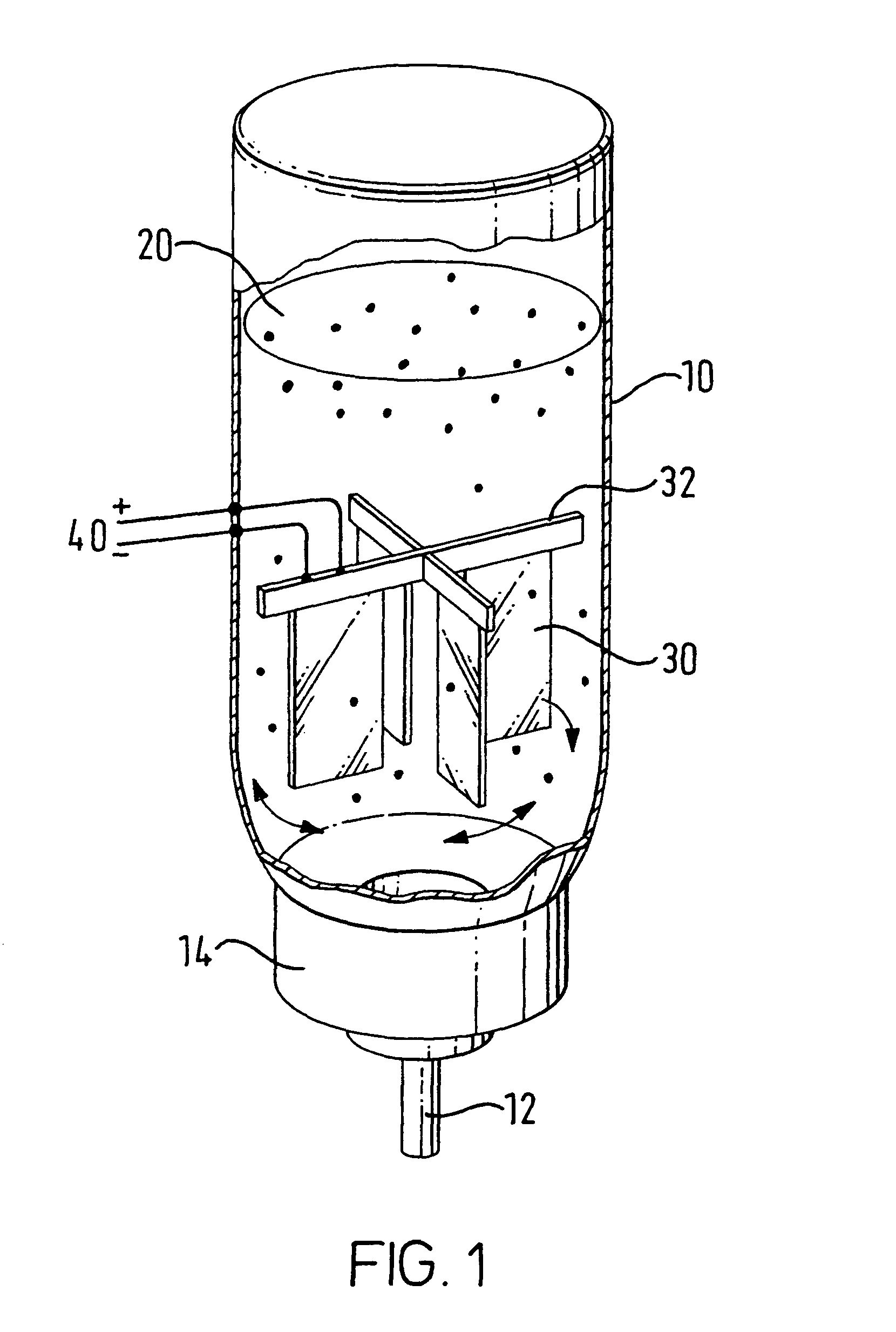
[0045]FIG. 1. shows a medicament dispenser suitable for use in a metered dose inhaler (MDI) for delivery of inhalable medicament. The dispenser comprises an aerosol can 10 having a dispenser outlet in the form of a metering valve 12. The valve gasket 14 is fixedly attached (typically by crimping) to the aerosol can body 10. The can 10 comprises a suspension 20 of medicament in a propellant.

[0046]Within the can 10 there are provided four vibratable flippers 30 mounted on cross-mounting 32. Each vibratable flipper 30 is comprised of a bimetallic strip which flexes on application of electrical current. In alternative embodiments, the flippers may also comprise piezoelectric materials. The cross-mounting 32, and hence each flipper 30, is connected to external electric power source40 which may be in the form of a battery or a capacitor. On application of electric power the flippers 30 vibrate thereby resulting in agitation of the suspension 20.

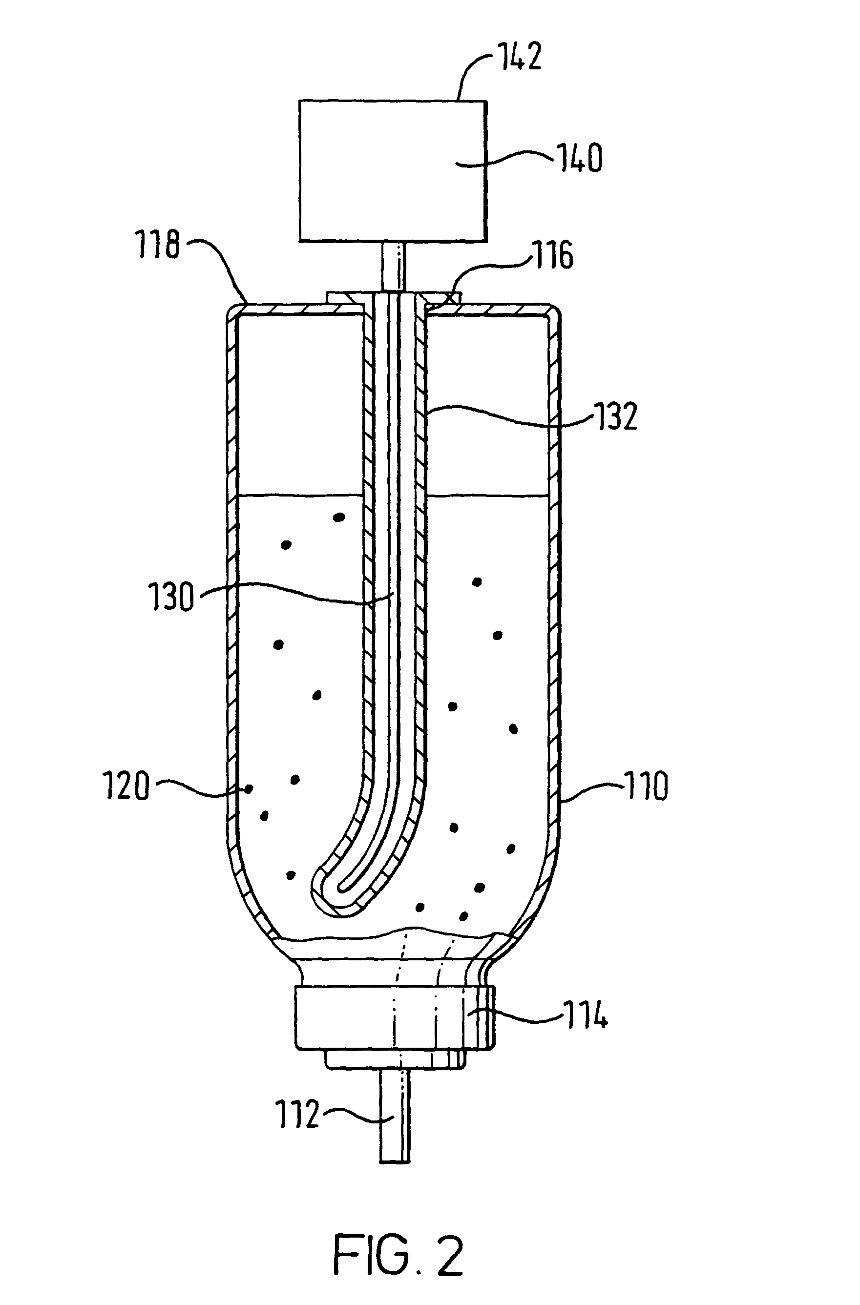
[0047]FIG. 2. also shows a medicament dispen...


PUM


Abstract

A medicament dispenser including a medicament container having a dispensing outlet; an agitator for agitating the contents; and a driver for driving the agitator independent of any container movement. The medicament container may be a metered dose inhaler or delivering a suitable inhalable medicament.

Description

[0001]The instant application is filed under 35 U.S.C. § 371 as the United States National Phase Application of International Application No. PCT / EP00 / 09641 filed 28 Sep. 2000 claiming priority from GB 9924808.0 filed 21 Oct. 1999.TECHNICAL FIELD[0002]This invention relates to a medicament dispenser including an agitator for agitating the medicament contents thereof. The dispenser is particularly suitable for use as an inhalation device.BACKGROUND TO THE INVENTION[0003]Known medicament dispensers comprise a medicament container having a dispensing outlet for dispensing of the medicament therefrom. Such medicament dispensers often require the patient to agitate the contents thereof prior to dispensing to ensure ready and uniform dispensing of the medicament. The agitation involves a manual shaking action.[0004]Agitation is particularly required where the dispenser comprises medicament as a suspension in a propellant formulation. A well-known example of this type is the metered dose i...

Claims


Application Information

Patent Timeline
IPC IPC(8): A61M11/00A61M15/00B01F11/00B05B1/08B67D5/64B01F7/00A61M15/02B01F13/08B01F15/00B05B15/00B05B15/25B65D83/14B67D7/84
CPCA61M15/009A61M15/0006B01F7/0005B01F7/00325B01F11/0071B01F11/0074B01F11/0088B01F13/0818B01F13/0827B01F15/00519B05B15/003B65D83/75A61M2205/8206A61M2205/8281A61M2205/0266B05B15/25B01F27/054B01F27/1126B01F31/651B01F31/65B01F31/445B01F33/4534B01F33/452B01F35/32025
Inventor RAND, PAUL KENNETH
Owner SMITHKLINE BECKMAN CORP
Why Eureka
Try Eureka