Connector cover for portable terminal

a technology for connecting cables and portable terminals, which is applied in the direction of coupling device details, substation equipment, coupling device connections, etc., can solve the problem of unsuitable structure for a small product, and achieve the effect of preventing dust from entering the casing and improving shortcomings

Inactive Publication Date: 2007-03-13
NEC CORP
View PDF17 Cites 23 Cited by
  • Summary
  • Abstract
  • Description
  • Claims
  • Application Information

AI Technical Summary

Benefits of technology

[0012]An object of the present invention is to improve shortcomings in the conventional art, and to provide a connector cover for a portable terminal which is hardly influenced by deformation and dimensional changes due to repetition of attaching / detaching operations or secular change, and capable of closing the opening of the casing securely so as to prevent dust from being entered inside the casing.

Problems solved by technology

However, since the span of the arm must be set to have a sufficient length, this structure is not suitable for a small product such as a connector cover for a portable terminal.

Method used


Image

  • Connector cover for portable terminal
  • Connector cover for portable terminal
  • Connector cover for portable terminal

Examples


example 1

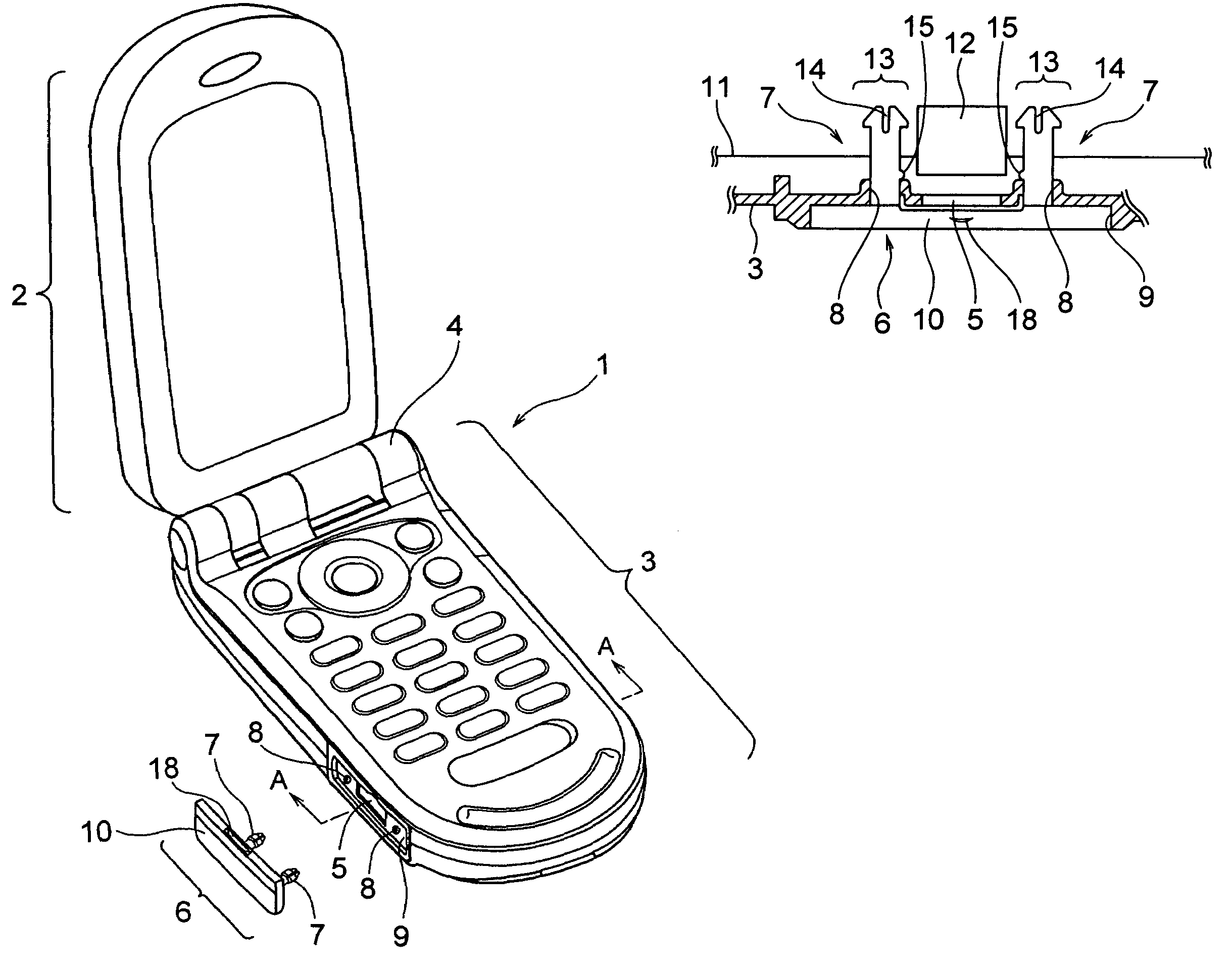
[0046]FIG. 3 is a horizontal sectional view partially showing the periphery of the mounting position of the connector cover 6, in the state where the mobile phone 1 is normally disposed as shown in FIG. 2, taken by a horizontal plane across the center part in the thickness direction of the casing 3. FIG. 4 is a vertical sectional view partially showing the periphery of the mounting position of the connector cover 6, taken along the line A—A of FIG. 2 across the casing 3.

[0047]As shown in FIG. 3, the casing 3 has the opening 5 formed corresponding to the arrangement position of a connector 12 for external connection fixed to the electronic circuit board 11 built in the casing 3, and is adopted to enable the connector cover 6 for covering the opening 5 to be mounted detachably.

[0048]Specifically, on both sides of the opening 5, the holes 8 and 8 with sleeve thick portions are perforated, into which the columnar connecting parts 7 and 7 of the connector cover 6 are inserted and fitted,...

example 2

[0061]FIG. 5 is a horizontal sectional view showing another example, in which the forming positions of the protruding portions 15 on the columnar connecting parts 7 are different from those of the example shown in FIG. 3. In the example of FIG. 3, the forming positions of the protruding portions 15 are relatively outward, and in the example of FIG. 5, the forming positions of the protruding portions 15 are relatively inward. However, this does not cause any specific difference in the operational effect.

[0062]Even in either example shown in FIG. 3 or FIG. 5, the protruding portion 15 consisting of a knob-like protrusion is formed at a place in the circumferential direction of the columnar connecting part 7. However, it is possible to form protruding portions 15 at several places in the circumferential direction of the columnar connecting part 7 within a range not causing a trouble in attaching / detaching operations of the connector cover 6 for a portable terminal.

example 3

[0063]FIGS. 6(a) and 6(b) show still another example. FIG. 6(a) is a horizontal sectional view partially showing the periphery of the mounting position of the connector cover 6, in the state where the mobile phone 1 is normally disposed as shown in FIG. 2, taken by a horizontal plane across the center part in the thickness direction of the casing 3. FIG. 6(b) is a front view showing the peripheral structure of the connector cover fitting groove 9 in the state of the connector cover 6 being removed from the casing 3.

[0064]In this example, a protruding portion 19 positioned at the base part of the columnar connecting part 7 is formed of a protruding strip, which is the structural difference from respective examples described above.

[0065]As shown in FIG. 6(a), the protruding portion 19 is a protruding strip protruded radially outward around the whole periphery at a place in the axial direction of the columnar connecting part 7. Accordingly, the shape is a ring flange substantially.

[006...


PUM


Abstract

To provide a connector cover for a portable terminal, capable of securely closing an opening in a casing so as to prevent dust from entering, without being influenced by deformation and dimensional changes due to secular change, etc. Protruding portions are formed on the base parts of the columnar connecting parts inserted and fitted in the holes in both sides of the opening, and the protruding portions engage with the holes from the rear face sides in the state of the columnar connecting parts having been inserted in the holes completely. Thereby, regardless of deformation and dimensional changes of the columnar connecting parts and the connector cover body due to secular change, etc., the connector cover can be kept at the completely closing position securely so as to prevent dust from entering into the opening.

Description

BACKGROUND OF THE INVENTION[0001]1. Field of the Invention[0002]The present invention relates to improvements in a connector cover for a portable terminal, for use in covering an opening formed in a casing of the portable terminal corresponding to the arrangement position of a connector for external connection.[0003]2. Related Art[0004]As a connector cover for a portable terminal covering an opening formed in a casing of the portable terminal, one disclosed in Japanese Patent Application Laid-open No. 2003-258964 (FIGS. 3 and 4, hereinafter referred to as Patent Document 1) is well-known. Further, as a general technique for securing a detachable covering member to the main body, a mounting structure of a decorative panel disclosed in Japanese Patent Application Laid-open No. 2001-317774 (FIGS. 6, 7 and 8, hereinafter referred to as Patent Document 2), for example, is well-known.[0005]FIG. 1 shows a conventional connector cover for a portable terminal disclosed in Patent Document 1 a...

Claims


Application Information

Patent Timeline
Patent Type & Authority Patents(United States)
IPC IPC(8): H01R13/44H01R13/443H04M1/02H01R13/52
CPCH01R13/443H04M1/0274
Inventor IIKURA, KENJI
Owner NEC CORP
Why Eureka
Try Eureka