
Optically and fluidically enhanced in vitro diagnostic test chamber

a technology of fluid enhancement, which is applied in the field of optically and fluidically enhanced in vitro diagnostic test chamber, can solve the problems of threads in general, threads, and threads that are of a lesser volume in the majority of cases, and achieve the effect of optimizing the light collection efficiency

Inactive Publication Date: 2007-03-13
HITACHI CHEM DIAGNOSTICS
View PDF12 Cites 0 Cited by
  • Summary
  • Abstract
  • Description
  • Claims
  • Application Information

AI Technical Summary

Benefits of technology

"The patent describes a system for screening liquid samples for allergic reactions using a chamber with multiple wells. The chamber is designed to minimize the volume of liquid needed and to efficiently detect the reaction. The system includes a coverslip, a bottom member, and an opaque partition to isolate the light path and enhance detection. The flow of fluid in the chamber is directed by a continuous surface and a flow-diverting member to improve washing. The system also includes a light path and partition system to concentrate the light emitted from the wells and minimize cross-over between them. The design of the chamber allows for optimal detection and washing with small volumes of patient serum."

Problems solved by technology

Unfortunately, pediatric samples in most cases are of a lesser volume.
Secondly, it has been determined that threads in general, and especially cotton threads, require large volumes of allergen / antigen / reactant in their absorption.
This rate of usage increases the cost of the test, as it requires very large-scale allergen extraction.
This is a disadvantage because it increases the cost of the product.
Additionally, the thread is a natural product (cotton) and it can be difficult and costly to control in quality from lot to lot.
Third, the alignment and registry of the individual threads between in the individual lands of the device required constant attention and effort.
Fourth, and once the threads have been incubated with reactants—such as serum—it is required that they be washed and drained.
With a straight flow path, washing of threads requires excessive fluid.
The incomplete or even inconsistent draining of the washing solution from the test chamber represents a potential dilution problem for the subsequent operation of the device, requiring the operator to ensure that all fluid is expelled from the chamber after washing.
Sixth, the coverslip is made of extruded polystyrene, which is prone to scratches and is difficult to manufacture necessitating QA efforts to select parts.

Method used


Image

  • Optically and fluidically enhanced in vitro diagnostic test chamber
  • Optically and fluidically enhanced in vitro diagnostic test chamber
  • Optically and fluidically enhanced in vitro diagnostic test chamber

Examples


Embodiment Construction

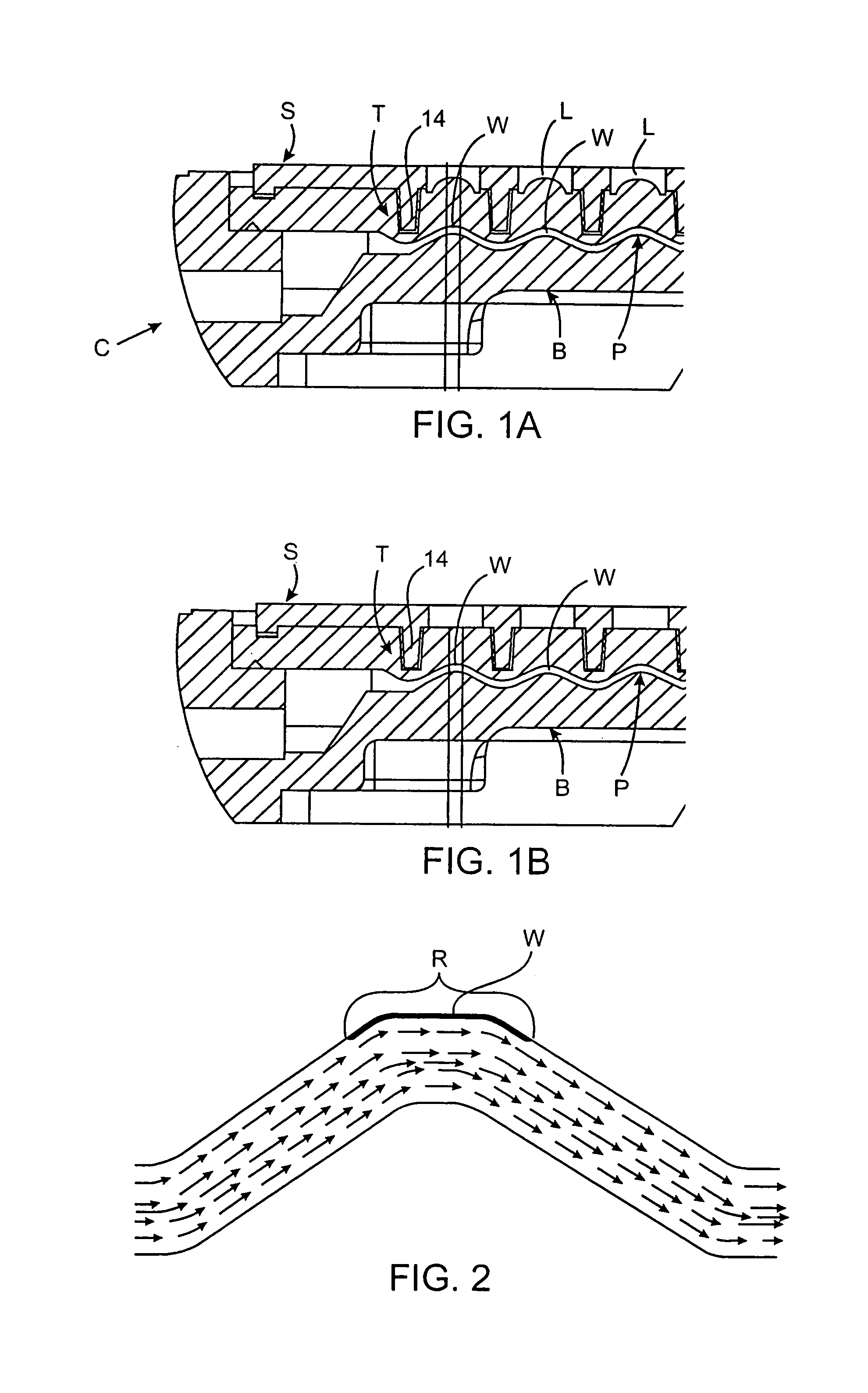
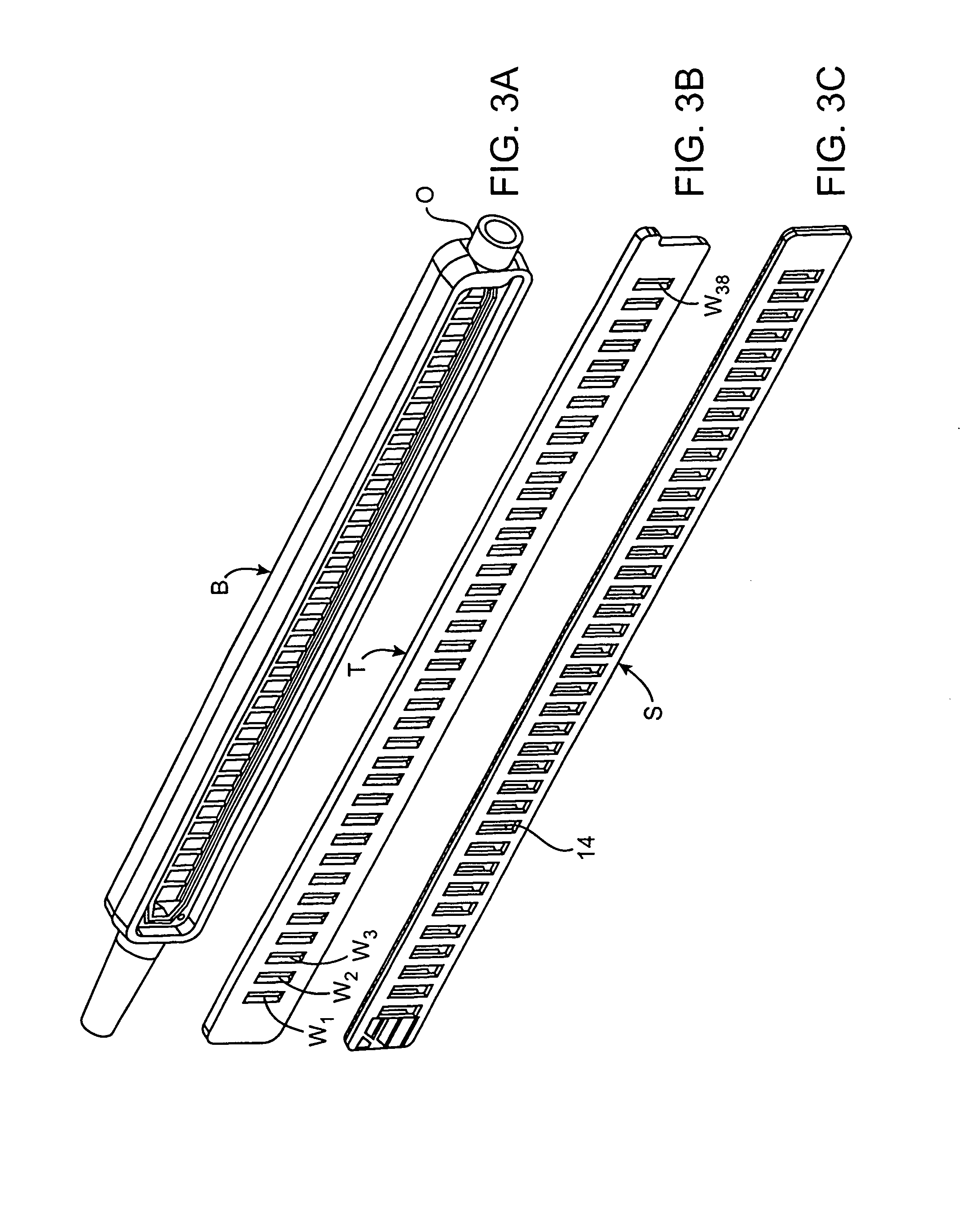
[0050]Referring to the side elevation section of FIG. 1A, an overall understanding of the assembled chamber C can be attained. Chamber C includes bottom B defining flow protrusions P. As will hereafter be set forth, it is the function of bottom B and flow protrusions P to provide an efficient cleansing action to the individual wells W containing the desired reactants R To aid in minimizing light carry-over, bottom B is made from a material, which absorbs light. We prefer the use of an opaque material that absorbs light as distinguished from materials, which in any way may be reflective.

[0051]Overlying bottom B and spaced apart from the bottom as shown in FIG. 1 is transparent member or coverslip T. Coverslip T serves three major functions. First and when inverted from the disposition shown in FIG. 1A and 1B, individual wells W receive reactants R. Reactants R adhere to the bottom of wells W when coverslip T is inverted. (See FIG. 2).

[0052]Second, transparent cover or coverslip T per...


PUM

PropertyMeasurementUnit
depthaaaaaaaaaa
depthaaaaaaaaaa
angleaaaaaaaaaa

Abstract

An enclosed chamber is used in a system for screening of a liquid specimen through binding assays. The enclosed chamber includes an inlet, an outlet, and a plurality of discrete reactant containing wells communicated by a common reagent flow path between the inlet and the outlet. A transparent member or coverslip defines on an inside thereof the plurality of wells. Each well has a bottom for receiving an allergent / antigen / reactant, which emits light upon reacting. The coverslip can optionally define at least one lens at each well. A bottom encloses the plurality of wells and defines between the inlet and the outlet a common reagent flow path between the inlet and the outlet. This bottom defines for each of the plurality of wells a flow-diverting member. An opaque partition is disclosed for surrounding the individual lenses and generally isolating the light path from each well.

Description

RELATED PATENT APPLICATION[0001]This application claims priority from US Provisional Patent Application Ser. No. 60 / 191,324 filed Mar. 21, 2000 and entitled OPTICALLY AND FLUIDICALLY ENHANCED IN VITRO DIAGNOSTIC TEST CHAMBER by the inventors herein.[0002]This invention relates to an apparatus and method for use in the diagnostic analysis of a liquid specimen through binding assays. More particularly, an optically and fluidically enhanced in vitro diagnostic test chamber and process of chamber utilization is disclosed over the apparatus and method disclosed in Sell et al U.S. Pat. No. 4,567,149 issued Jan. 28, 1986.BACKGROUND OF THE INVENTION[0003]In Sell et al U.S. Pat. No. 4,567,149 issued Jan. 28, 1986, an apparatus and a related method for use in the diagnostic analysis of a liquid specimen through binding assays was disclosed. The apparatus included a rigid body and a plurality of elongated threads, sometimes also referred to as filaments and / or strips, each coated with a bindin...

Claims


Application Information

Patent Timeline
Patent Type & Authority Patents(United States)
IPC IPC(8): G01N21/00C12Q1/68G01N15/06G01N31/22G01N33/00G01N33/53B01L3/00G01N21/03G01N21/25G01N21/76G01N37/00
CPCB01L3/5025G01N21/253G01N21/0303B01L2300/087B01L2400/0406Y10T436/11G01N21/76G01N2021/6482
Inventor INNERST, DIANNAKASSINOS, ADONISWOOLEY, C. BENJAMINWILMARTH, BRETTSELL, WILLIAM J.ZYCHLINSKY, EMIMARINO, DONALDYAMADA, SANDYRYAN, RENEEDING, KARENZATZKE, MICHAEL
Owner HITACHI CHEM DIAGNOSTICS
Learn More