Editing video data

a video data and video technology, applied in the field of original video data editing, can solve the problems of introducing artefacts, difficult to convert film images into video data, and jittering of images,

Active Publication Date: 2007-03-13
AUTODESK INC
View PDF7 Cites 8 Cited by
  • Summary
  • Abstract
  • Description
  • Claims
  • Application Information

AI Technical Summary

Problems solved by technology

It is also well known that high quality cinematographic film is displayed at twenty-four frames per second, therefore there is an inherent difficulty in terms of converting film images into video data.
A further complication with commercial video systems is that each frame is generated from two interlaced fields therefore it is more correct to think in terms of generating ten output fields from four input frames.
However, in addition to this, two frames are constructed in which interlaced fields are derived from different input frames such that when viewed as a still frame, there is a tendency for the image to jitter, particularly if movement has occurred between the two source frames.
However, given that material must be written back to an inserted video stream, known systems only allow edits at the boundaries between a D Frame and an A Frame, that is to say, at the start of the insertion cycle.
Consequently, material that has been processed in this way introduces a further limitation into the editing process which may result in artistic compromises being made or may result in the introduction of artefacts.

Method used


Image

  • Editing video data
  • Editing video data
  • Editing video data

Examples


Embodiment Construction

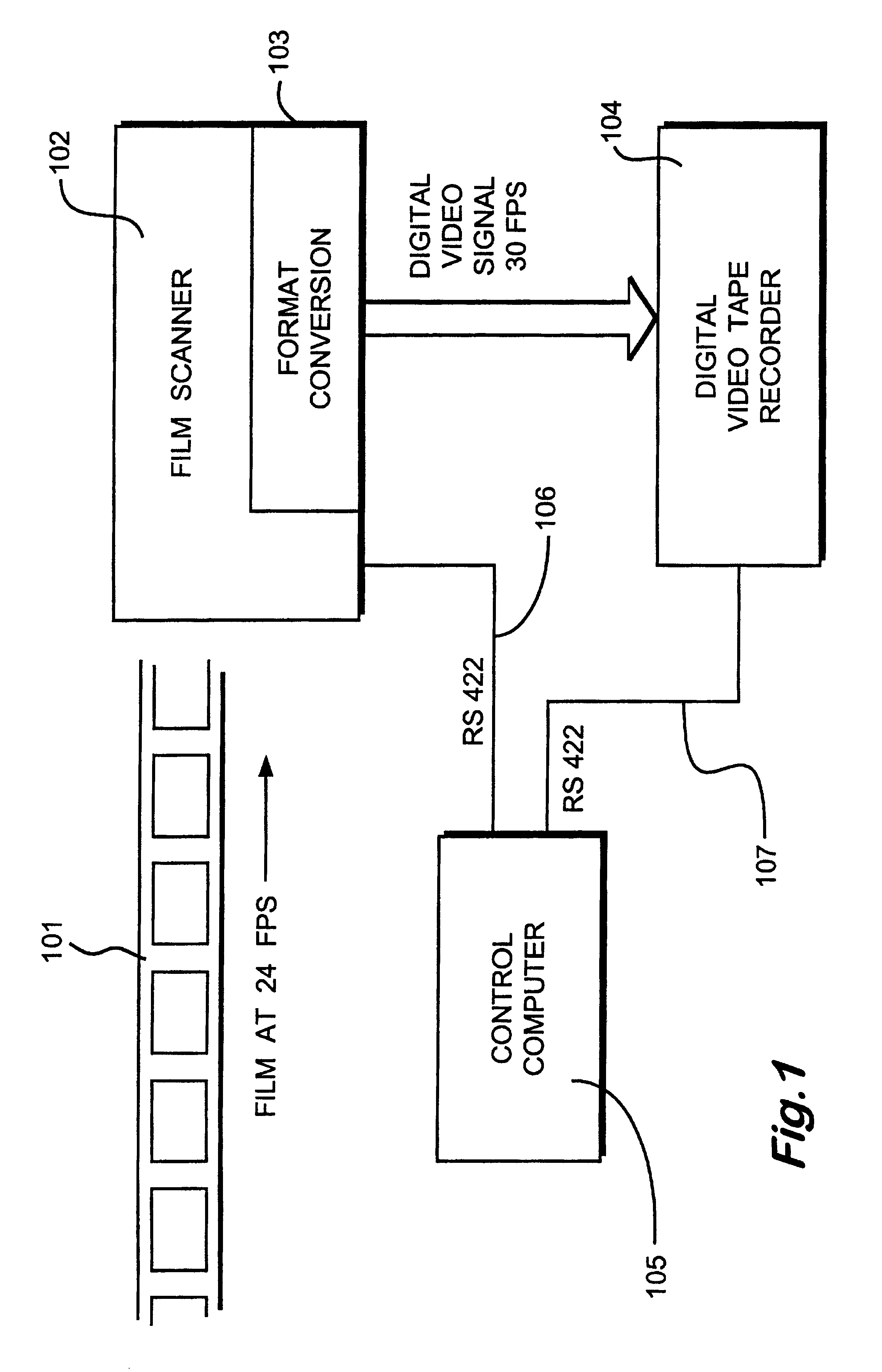
[0019]A system for recording cinematographic film onto digital video tape is illustrated in FIG. 1. Cinematographic film stock 101, configured to be displayed at a rate of twenty-four frames per second is received by a film scanner 102, configured to generate high definition video signals at an off-line speed less than the real-time display rate.

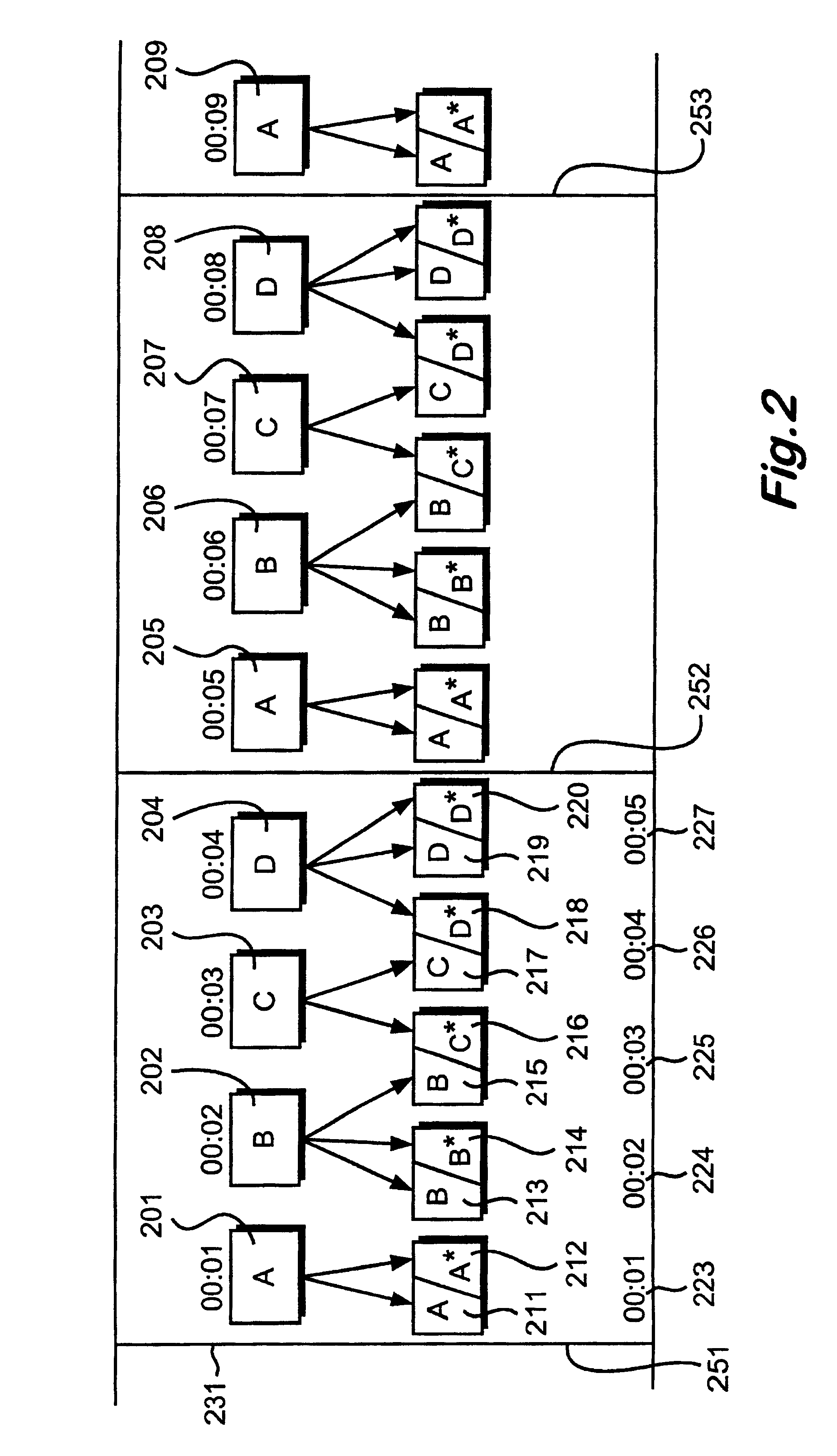
[0020]Film scanner 102 includes a format conversion process 103 arranged to convert image signals scanned at 23.98 frames per second (notionally twenty-four frames per second) into a digital video signal with frames at 29.97 frames per second (notionally thirty frames per second). The thirty frame per second digital video signal is supplied to a digital video tape recorder 104 and both the film scanner 102 and the digital video tape recorder 104 are controlled by a control computer 105 over RS422 serial interfaces 106 and 107.

[0021]Format conversion process 103 is illustrated in FIG. 2. Film scanner 102 produces a progression of frames deriv...


PUM

PropertyMeasurementUnit
time-codeaaaaaaaaaa
frequencyaaaaaaaaaa
speedaaaaaaaaaa

Abstract

Original video data of a first format is edited. The first format video data has jitter frames (626) inserted therein and is displayed at a first frame rate. The original video data is read from a video tape recorder (301) in the first format and converted into a second format with no jitter frames, displayable at a second display rate. Time-code of the converted video data is related to time-code of the original video data so as to identify frame types for the converted video data. A portion (603-606) of the converted video data is modified to produce modified video data in the second format. New video data is generated in the first format by processing the modified video data. An edit processor is configured to replace an edit portion of the stored original data with the new data by defining an edit range with reference to the new data, selecting an edit field with reference to the frame type so as to initiate an edit on a data boundary. New data is written to the video tape recorder and an edit field is selected again before completing the writing process. In this way, video edits occur at positions that are consistent with data boundaries irrespective of the selected edit position.

Description

BACKGROUND OF THE INVENTION[0001]1. Field of the Invention[0002]The present invention relates to editing original video data of a first format, wherein said first format has inserted jitter frames and is displayable at a first frame rate.[0003]2. Description of the Related Art[0004]It is well known that commercial video systems operate at thirty frames per second, slightly less than thirty frames per second (NTSC drop frame) or twenty-five frames per second; rates determined primarily by the frequency of AC mains supplies. It is also well known that high quality cinematographic film is displayed at twenty-four frames per second, therefore there is an inherent difficulty in terms of converting film images into video data.[0005]A process of 2:3 insertion for converting from twenty-four frames per second to thirty frames per second is well known and results in five output frames being generated from four input frames on a repeating cycle. Input frames making up the cycle are usually re...

Claims


Application Information

Patent Timeline
Patent Type & Authority Patents(United States)
IPC IPC(8): G11B27/00G11B27/02G11B5/027G11B27/032G11B27/034H04N7/01
CPCG11B27/034H04N7/0112G11B27/032G11B2220/2545G11B2220/213
Inventor BOLDUC, MARC
Owner AUTODESK INC
Why Eureka
Try Eureka