Connector, band and watch

a technology of connectors and bands, applied in the direction of bracelets, chain elements, shackles, etc., can solve the problems of connectors falling out during use, the protruding dimensions change due to elastic deformation, etc., and achieve the effect of stable fixing for

Active Publication Date: 2007-03-20
SEIKO EPSON CORP
View PDF13 Cites 13 Cited by
  • Summary
  • Abstract
  • Description
  • Claims
  • Application Information

AI Technical Summary

Benefits of technology

[0004]An object of the present invention is to provide a connector whereby a stable fixing force can be obtained even with repeated use, and to provide a band that has this connector.

Problems solved by technology

Such a case has problems in that when the connector is repeatedly inserted and removed in the through-hole to adjust the band length, the dimensions of the protrusion change due to the elastic deformation.
When such a connector is used, there is the possibility that the connector will fall out during use due to the reduction in the fixing force.

Method used


Image

  • Connector, band and watch
  • Connector, band and watch
  • Connector, band and watch

Examples


working examples

[0086]The following experiments were conducted to confirm the effects of the present invention.

working example 1

[0087]An experiment was conducted using the connecting pin 3 of the third embodiment (FIG. 8).

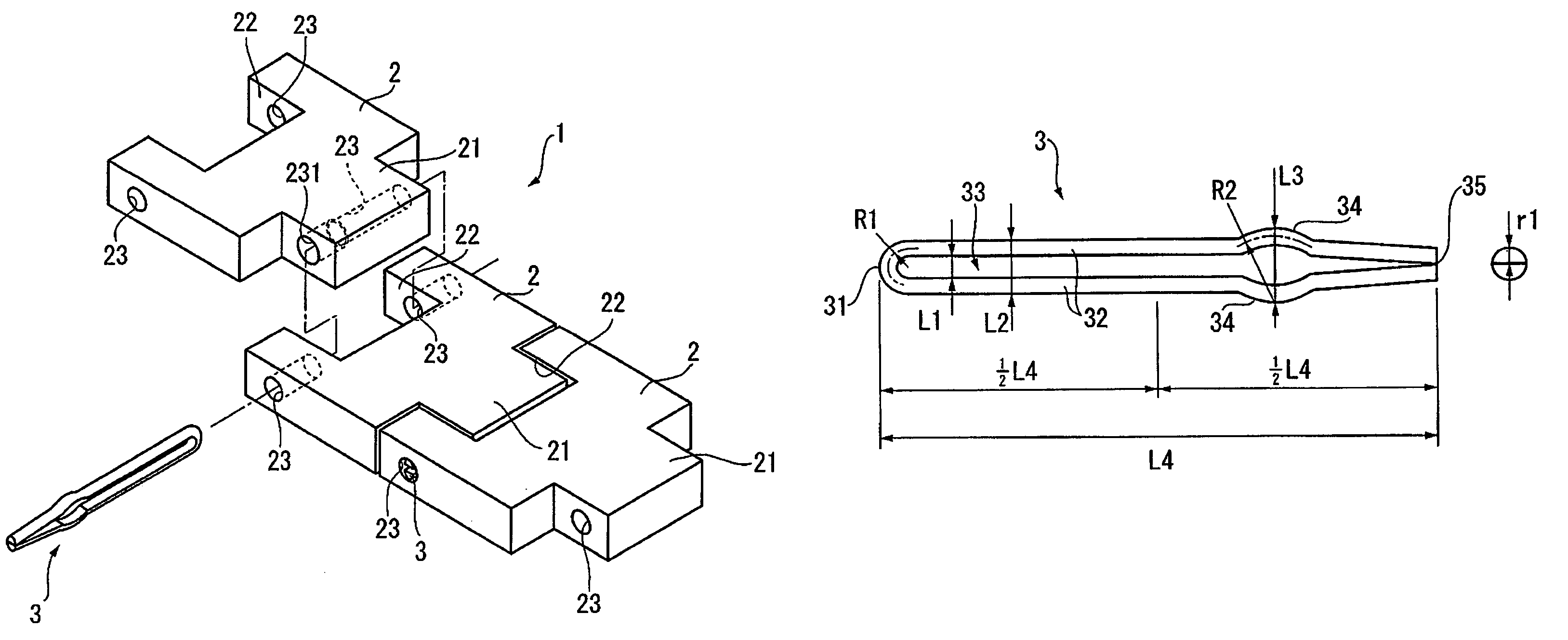
[0088]The distance L6 from the proximal ends of the protrusions 34 in the connecting pin 3 to the contact section 36A was 2.0 mm, and the distance L7 from the proximal ends of the protrusions 34 to the contact section 35 was 2.0 mm. Also, the distance L1 between the pair of linear parts 32 was 0.1 mm, and the entire length L4 of the connecting pin 3 was 14 mm. Furthermore, the difference between the distance L3 between the protrusions 34 and the diameter D1 of the inner periphery of the through-hole 23 was set to 0.1 mm.

[0089]The connecting pin 3 was repeatedly (seven times) inserted into and withdrawn from the through-hole 23, and the pulling force thereof was measured.

working example 2

[0090]An experiment was conducted using the connecting pin 3 shown in FIG. 13.

[0091]The distance L6 from the proximal ends of the protrusions 34 in the connecting pin 3 to the contact section 36A was 1.0 mm, and the distance L7 from the proximal ends of the protrusions 34 to the contact section 36D was 1.0 mm. Also, the difference between the distance L3 between the protrusions 34 and the diameter D1 of the inner periphery of the through-hole 23 was set to 0.08 mm. The conditions were otherwise the same as in Working Example 1.


PUM


Abstract

The band relating to the present invention includes a first block, a second block, and a connector. The first connector has a concavity and first and second through-holes disposed on both sides of the concavity. The second block as a convexity that interlocks with the concavity and that has a third through-hole. The connector is inserted through the first, second, and third through-holes. The connector has a first linear part, a second linear part, and a folded portion that connects the first and second linear parts. The first linear part has a first rectilinear part extending from the folded portion and separated from the second linear part in a free state, a first protrusion extending from the first rectilinear part and protruding away from the second linear part, and a first end extending from the proximal end of the first protrusion away from the folded portion. The first end has a first tip disposed such that the distance thereof to the second linear part is shorter than the distance to the second linear part from the proximal end of the first protrusion in a free state.

Description

FIELD OF THE INVENTION[0001]The present invention relates to a connector for connecting adjacent members to each other, and a band and timepiece provided with this connector, and relates to, for example, a connector for connecting the block members in the band of a timepiece, and a band and timepiece provided with this connector.DESCRIPTION OF THE RELATED ART[0002]One example of a method for connecting a plurality of blocks to each other in a band or the like of a timepiece involves forming through-holes in the ends of the blocks, and inserting a common connector through these through-holes (for example, Japanese Patent Application Laid-Open No. 10-80307, pp. 7–8, FIG. 2). This connector is made of a cross-sectional turtleback-shaped metal wire folded in two. A part of the metal wire is bent to form an outward protrusion. A large-diameter region that is larger than the inner periphery of the through-holes is formed in the through-holes of the blocks, and when the connector is insert...

Claims


Application Information

Patent Timeline
Patent Type & Authority Patents(United States)
IPC IPC(8): F16G15/04A44C5/10
CPCA44C5/105
Inventor YAMAMOTO, AKIO
Owner SEIKO EPSON CORP
Why Eureka
Try Eureka