Resection guide, trial knee joint implant, and surgical instrument for knee arthroplasty

a knee joint implant and surgical instrument technology, applied in the field of knee joint surgery surgical instruments, can solve the problems of insufficient support for forces generated, increased number of patients with knee joints that are incurably damaged, and increased risk of quadriceps femoris weakening

Active Publication Date: 2020-08-25
CORENTEC
View PDF12 Cites 0 Cited by
  • Summary
  • Abstract
  • Description
  • Claims
  • Application Information

AI Technical Summary

Benefits of technology

[0017]An objective of the present invention is to provide a resection guide enabling implantation of an implant providing stable fixing force by having high resistance to rotation and to external forces on a coronal plane and a sagittal plane.
[0066]The present invention provides a resection guide, a trial knee joint implant, and a surgical instrument for knee arthroplasty, all of which enable implantation of an implant having a protrusion that protrudes from a contact surface of the implant, which is to come into contact with a resected surface of a bone, wherein the protrusion engages with a sliding groove formed in the resected surface of the bone and has a portion expanded in a direction perpendicular to a direction in which the protrusion protrudes to have convex-curved surfaces, whereby the protrusion has an overall circular cylinder shape, thereby preventing concentration of stress and ensuring stable fixing force without causing damage to a bone.

Problems solved by technology

Since the knee joint is frequently used and is likely to be overworked, the number of patients with knee joints that are incurably damaged is gradually increasing due to wear of knee joints, aging of bone tissues, accidents, and the like.
A problem such as weakening of a quadriceps femoris muscle is likely to occur when knee joints are not used for a long period of time.
Also, aseptic loosening, unexplained pain, and an implant-Poly Methyl Methacrylate (PMMA) construction that provides insufficient support for forces generated by patient activities and body habitus are posed as disadvantages.
Due to limited exposure and lack of access to the posterior side of the knee, using an optimal cement technique is challenging.
Also, since surgeons often use a limited amount of PMMA during UKA, initial implant fixation is less than optimal.
In particular, uncemented implant fixation of cementless UKA can cause bone remodeling concomitant with structural enhancement and reduce a possibility of aseptic loosening caused by bone failure.
However, despite the many advantages, the cementless or uncemented UKA and TKA still have room for improvement. FIGS. 1 to 7 show problems with conventional uncemented UKA and TKA.
It can be understood based on the drawings that it is difficult to ensure stable initial implant fixation.
Moreover, as illustrated in FIG. 4, in the case of a UKA femoral component 50, since forces applied to a joint are parallel to fixation pegs 52, the UKA femoral component 50 is likely to perform rocking motion, leading to bone ingrowth failure.
Since the tibial component 30 is loaded from the top, the tibia must be dislocated as illustrated in FIG. 5, leading to a complicated and invasive surgical procedure.
Since 70 to 80 percent of patients who receive TKA have normal anterior cruciate ligaments, removal of the normal anterior cruciate ligaments is undesirable and a BCR tibial component is thus used.
Since the cruciate bone island 1000 has sharp corners (denoted by an arrow) attributable to resection of an articular surface, stress on the corners increases, thereby often causing avulsion fracture of a bone.

Method used


Image

  • Resection guide, trial knee joint implant, and surgical instrument for knee arthroplasty
  • Resection guide, trial knee joint implant, and surgical instrument for knee arthroplasty
  • Resection guide, trial knee joint implant, and surgical instrument for knee arthroplasty

Examples


first embodiment

[0106]With reference to FIGS. 8, 10A and 10B, a resection guide 1 according to the present invention is used for resection of a proximal end of a tibia during total knee arthroplasty (TKA). The resection guide 1 includes a main body 11 and two fixing pins 13.

[0107]The main body 11, as illustrated in FIGS. 10A and 10B, is arranged on an anterior surface of a proximal end of a tibia 10 such that the proximal end of the tibia 10 is resected by a resection device (not illustrated). The main body 11 includes a guide portion 111 formed to pass through the main body 11, a window 113, and two auxiliary pin insertion holes 115.

[0108]The guide portion 111 includes a slot 1111 that guides movement of the resection device and two pin insertion holes 1113 formed to communicate with the slot 1111 such that the fixing pins 13 can be inserted into the pin insertion holes 1113, respectively.

[0109]The slot 1111 transversely extends across the main body 11 and guides the resection device such that the...

second embodiment

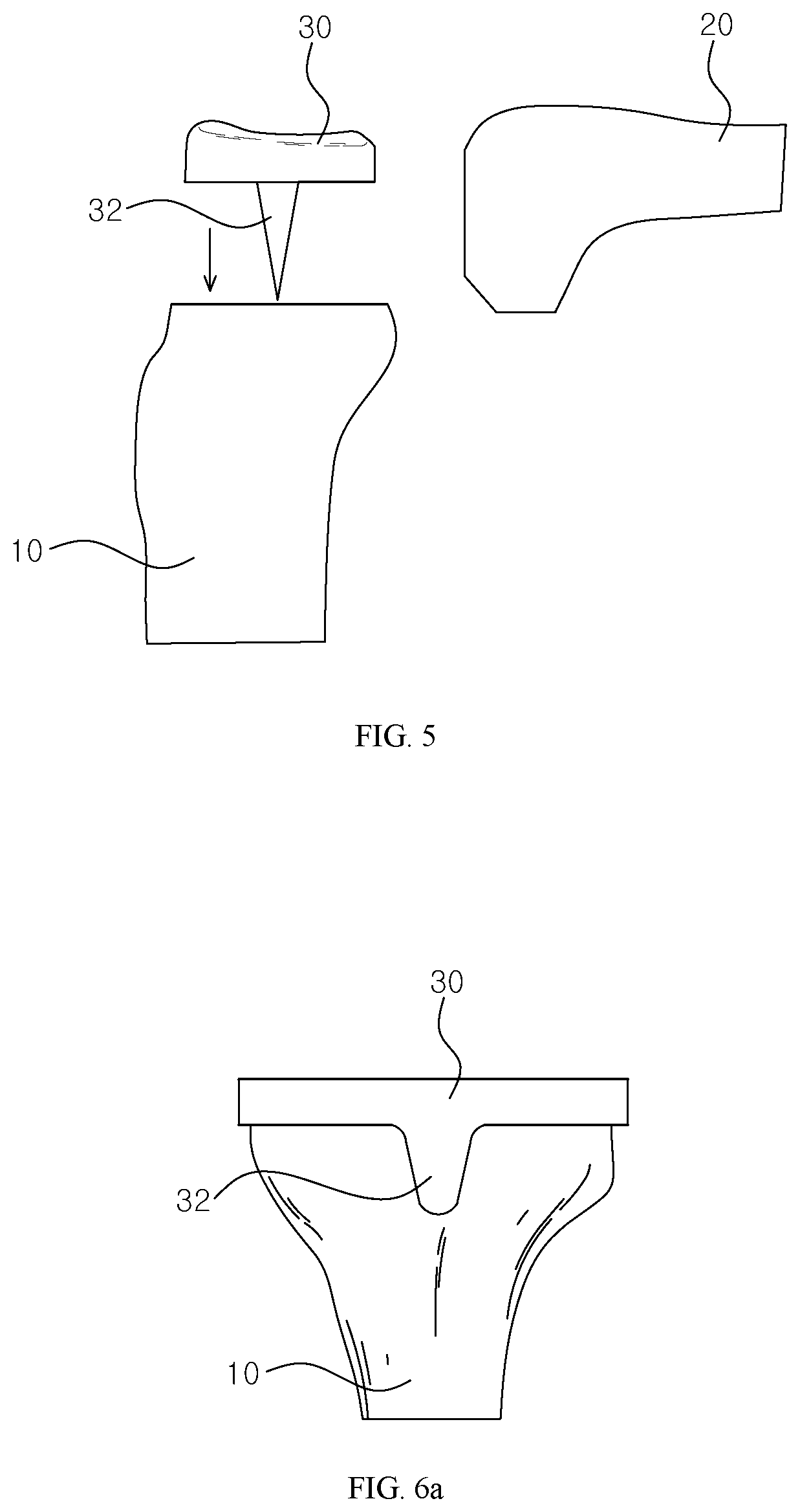
[0131]With reference to FIGS. 16 and 17, a resection guide 3 according to the present invention will be described. The resection guide 3 is used to guide resection of a proximal end of a tibia during unicompartmental knee arthroplasty (UKA). The resection guide 3 includes a main body 31 and a fixing pin 33.

[0132]The main body 31 is a component to be arranged on the anterior surface of a proximal end of a tibia 10 to guide a resection device (not illustrates) that resects the proximal end of the tibia 10. The main body 31 includes a guide portion 311 formed to pass through the main body 31, a window 313, and an auxiliary pin insertion hole 315.

[0133]The guide portion 311 includes a slot 4111 that guides movement of the resection device and a pin insertion hole 311 that is formed to communicate with the slot 3111 and into which the fixing pin 33 is inserted.

[0134]The slot 3111 extends in a medial-lateral direction, and an end of the slot 3111 in a direction along which the resection d...

third embodiment

[0148]With reference to FIG. 22, a resection guide 5 according to the present invention will be described. The resection guide 5 is used to guide resection of a distal end of a femur during UKA or TKA surgery, and includes a main body 51 and a fixing pin 53.

[0149]The main body 51 is arranged on the lateral surface or the medial surface of the distal end of the femur 20 such that the distal end of the femur 20 is resected by a resection device (not illustrated). The main body 51 includes a guide portion 511 formed to pass through the main body 51.

[0150]The guide portion 511 includes a slot 5111 that guides movement of the resection device and a pin insertion hole 5113 that is formed to communicate with the slot 5111 and into which a fixing pin 51 is inserted.

[0151]The slot 5111 includes a first slot 51111 vertically extending across the main body 51, a second slot 51113 extending toward a posterior side of the main body 51 from a lower end of the first slot 51111, and a third slot 51...


PUM


Abstract

Disclosed is a resection guide, a trial knee joint implant, and a surgical instrument for knee arthroplasty. The resection guide, the trial knee joint implant, and the surgical instrument enable implantation of an implant that provides improved vertical fixing force and initial fixing force as compared with an existing cementless or uncemented implant.

Description

CROSS-REFERENCE TO RELATED APPLICATIONS[0001]This application claims the benefit of U.S. Provisional Application No. 62 / 407,316, filed Oct. 12, 2016, which is incorporated herein by specific reference.FIELD OF THE INVENTION[0002]The present invention relates generally to a resection guide, a trial knee joint implant, and a surgical instrument for knee arthroplasty. More particularly, the present invention relates to a resection guide, a trial knee joint implant, and a surgical instrument for knee arthroplasty, all of which enable implantation of an implant providing improved vertical fixing force and initial fixing force in comparison with conventional cementless or uncemented implants.DESCRIPTION OF THE RELATED ART[0003]A knee joint refers to a joint formed between three bones: a femur, a tibia, and a patella. Knee joints are provided in the left and right legs support a body's weight and are essential for leg-involved movements such as walking and running. Since the knee joint is ...

Claims


Application Information

Patent Timeline
Patent Type & Authority Patents(United States)
IPC IPC(8): A61B17/58A61B17/15A61F2/38A61B17/17A61F2/30A61F2/46A61B17/02A61B17/88
CPCA61B17/155A61F2/4684A61B17/154A61F2/389A61B17/157A61F2/46A61B17/1764A61F2/38A61F2/3859A61F2/30771A61F2/3886A61F2002/3895A61F2002/30606A61F2002/30883A61B17/88A61B2017/0268
Inventor SHARKEY, PETER F.PARVIZI, JAVAD
Owner CORENTEC
Why Eureka
Try Eureka