
Aspheric soft lens

a silicone lens and apheric lens technology, applied in the field of aphakic lenses, can solve the problems of incompatibility of procedures, many pitfalls in estimating the basic refraction, and lack of continuum in the dioptric range, so as to achieve optimal postoperative vision, facilitate and safely implant the effect of the patient's eye, and convenient manufacturing

Inactive Publication Date: 2007-03-20
JOHNSON & JOHNSON SURGICAL VISION INC
View PDF69 Cites 9 Cited by
  • Summary
  • Abstract
  • Description
  • Claims
  • Application Information

AI Technical Summary

Benefits of technology

The present invention provides an intraocular aspheric silicone lens with a full dioptric range and method of making such a lens. The lens has a unique shape that allows for optimal postoperative vision and is designed for the surgical correction of aphakia following extracapsular cataract extraction. The lens can be easily and safely implanted in a patient's eye and provides optimal vision at both near and far distances. The lens is produced using a reverse molding process and can be easily and safely attached to haptics for the treatment of aphakia. The invention also provides a method of calculating dioptric power at any point on the lens.

Problems solved by technology

Experience has shown however that there are many pitfalls in estimating the basic refraction in this way, in view of the high incidence of residual anisometropia and aniseikonia cases in patients thus corrected.
These IOL's, however, provide near and distance vision but do not provide a continuum in the dioptric range.
Unfortunately, this procedure is not compatible with the insertion of hard PMMA lenses, and surgeons have found it necessary to increase the length of the incision to at least 8 mm to insert such lenses, obviating at least one advantage of phacoemulsification technology.
A problem with making such lenses is the difficulty in obtaining a satisfactory mold of optical quality, having the desired changing radius of curvature.
The resultant mold yields a lens having squared-off edges, which cannot be dramatically altered to provide a smooth, radiused edge without substantial risk of damaging the lens.
Due to the size of the mold and the difficulties in obtaining an optical finish on a convex surface produced by such a mold, molds for intraocular lenses, having critically measured multiple radii or aspherical portions, using present techniques is very difficult to make and not cost effective.
Haptic materials have included metal loops of various types, however, due to complications related to weight and fixation, such structures have proven undesirable.
It is imperative that the haptics not become detached from the optical element after implantation, as this could have severe repercussions.
One problem associated with such a mechanical bonding technique is that the mechanical anchor often intrudes into the optical zone of the lens, adversely affecting the visual acuity of the patient.
Problems also arise when the haptic material is heated to the molding temperature.
In general, excessive heat causes the haptic material to become brittle and causes degradation of the material.
Further, proper angulation of the haptic with respect to the lens is very difficult to achieve during standard molding processes, as the introduction of the lens material into the mold cavity can cause the haptics to be slightly offset.
In addition, the haptics tend to get smashed as the two halves of the mold are brought together and closed.
A lens rejected for lack of optical quality would obviate the proper positioning and attachment of the haptics thereto.
It would therefore be preferable to attach the haptics to the lens after the lens has been formed and optically tested, however, as mentioned above, the bonding of polypropylene to silicone has proven extremely difficult.

Method used


Image

  • Aspheric soft lens
  • Aspheric soft lens
  • Aspheric soft lens

Examples


first embodiment

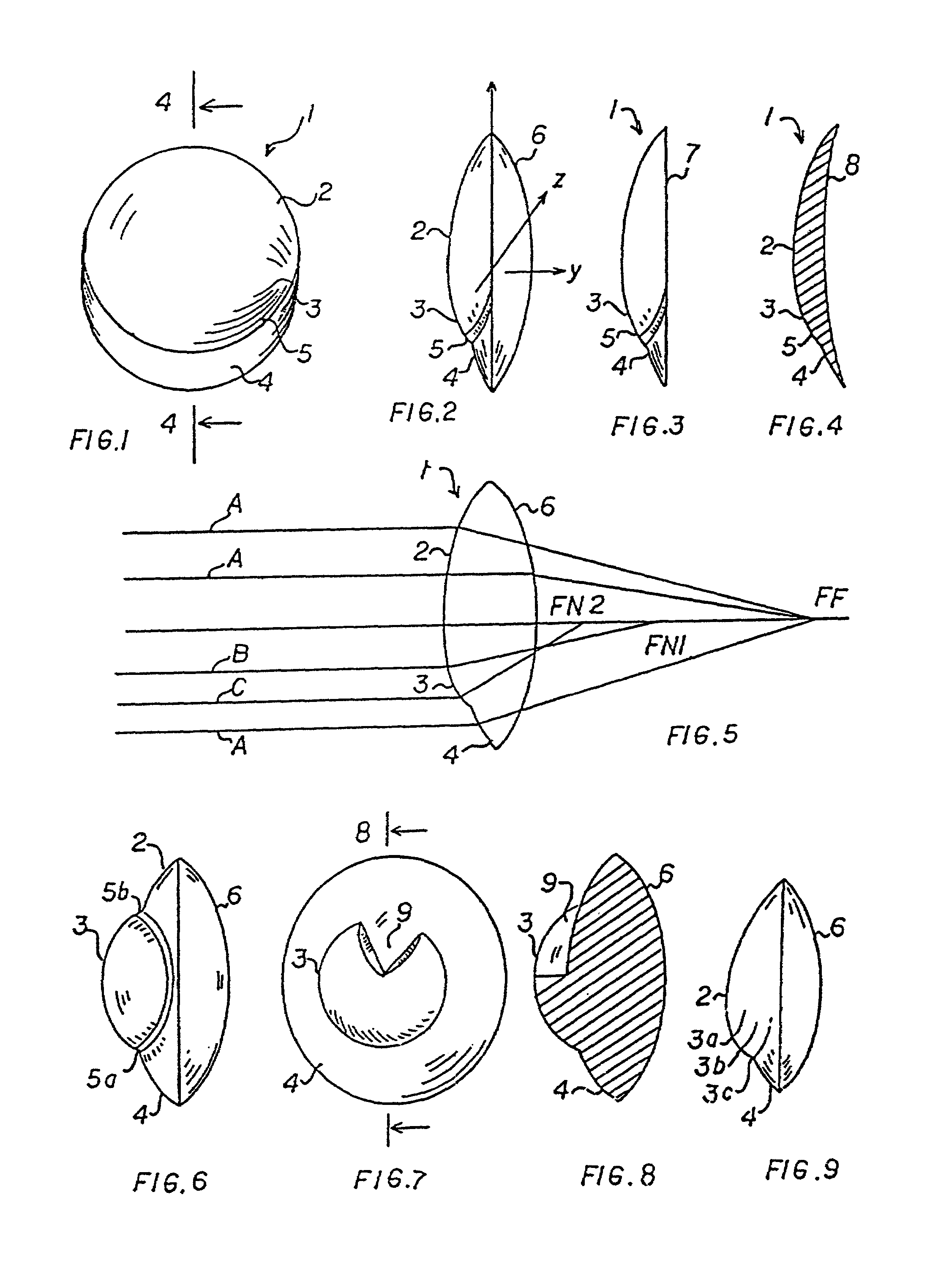
[0065]Now turning to FIG. 2, there is illustrated the present invention in a side view. The proximal side 6 is a convex surface in this embodiment. As illustrated in FIG. 1, the distal side 1 shows the three sectors hereabove described, namely the upper spherical sector 2, the central aspherical sector 3 and the lower spherical quarter 4.

[0066]In FIGS. 3 and 4, there are illustrated two other embodiments of the present invention. In FIG. 3, the proximal side 7 is a plane, whereas in FIG. 4, the proximal side 8 is a concave surface. In each of the aforementioned embodiments, the distal side has the same configuration.

[0067]FIG. 5 is an explanatory optical diagram illustrating the multifocal property of the first preferred embodiment of the present invention as described hereabove. It should be noted, however, that the optical diagram of FIG. 5 holds true for the other embodiments of the present invention. A ray of light A impinging upon the lens on its spherical sector 2 is focused i...

fourth embodiment

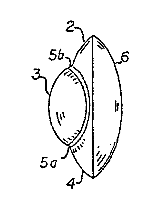
[0068]Now turning to FIG. 6, there is represented a side view of the present invention wherein the aspherical sector 3 extends approximately from the lower quarter 4 to the upper quarter 2. This aspherical sector 3 therefore defines two discontinuities 5a and 5b which can be both blocked out to eliminate glare as stated hereinbefore.

fifth embodiment

[0069]In the fifth embodiment illustrated in FIGS. 7 and 8, the aspherical sector 3 extends over the entirety of the central part of the intraocular lens as in FIG. 6 with the exception of an angular sector 9 in the upper part of the lens. More generally, the aspherical sector 9 can take various shapes. The number of degrees of the aspherical sector in the plane of the lenticulas can vary from 180 degrees to 360 degrees as in FIG. 6 and can take any intermediary value, as illustrated in FIG. 7. A value inferior to 180 degrees is not excluded but may impair the near vision properties of the intraocular lens.


PUM

PropertyMeasurementUnit
lengthaaaaaaaaaa
angleaaaaaaaaaa
angleaaaaaaaaaa

Abstract

An aspheric soft intraocular lens, having an optical power surface, which may have multiple radii portions or aspherical portions, as well as spherical portions, intended to replace the crystalline lens of a patient's eye, in particular after a cataract extraction. Such an aspheric soft lens is molded in a coined mold. A pair of core pins, positioned within the mold cavity during the lens forming process, will produce a pair of haptic-mounting holes within the lens. As the lenses are subsequently tumbled to remove flash, indentations will form adjacent to the haptic-mounting holes. These indentations allow for tangential attachment of the haptic to the lens which, in turn, enables maximum flexibility without exceeding the width of the optic.

Description

CROSS REFERENCE TO RELATED APPLICATIONS[0001]This application is a continuation of prior application 09 / 022,707, filed on Feb. 12, 1998, now abandoned, which is a continuation application of Ser. No. 08 / 161,194, filed on Dec. 1, 1993, now U.S. Pat. No. 6,797,003, which is a continuation application of Ser. No. 08 / 028,522, filed on Mar. 10, 1993, now abandoned, which is a continuation application of Ser. No. 07 / 626,736, filed on Dec. 13, 1990, now abandoned, which is a continuation-in-part of two applications: (1) Ser. No. 07 / 262,985, filed on Oct. 26, 1988, now U.S. Pat. No. 5,104,590, and (2) Ser. No. 07 / 509,871, filed on Apr. 16,1990, now U.S. Pat. No. 5,019,099, which is a continuation application of Ser. No. 07 / 232,140, filed on Aug. 15, 1988, now U.S. Pat. No. 4,917,681, which is a divisional application of Ser. No. 07 / 088,227, filed on Aug. 24, 1987, now U.S. Pat. No. 4,769,033.BACKGROUND OF THE INVENTION[0002]The present invention relates generally to the field of aphakic len...

Claims


Application Information

Patent Timeline
Patent Type & Authority Patents(United States)
IPC IPC(8): A61F2/16B29C33/00B29C33/76B29D11/02
CPCA61F2/1618B29D11/023B29C33/0033B29C33/76B29D11/00971B24B13/0006A61F2002/164A61F2002/1686A61F2/164
Inventor BLAKE, LARRY W.NORDAN, LEE T.
Owner JOHNSON & JOHNSON SURGICAL VISION INC
Learn More