Eureka AIR delivers breakthrough ideas for toughest innovation challenges, trusted by R&D personnel around the world.

Portable wireless terminal device

Inactive Publication Date: 2007-03-20
KYOCERA CORP
View PDF10 Cites 28 Cited by
  • Summary
  • Abstract
  • Description
  • Claims
  • Application Information

AI Technical Summary

Benefits of technology

[0009]An object of the present invention is to provide a portable wireless terminal device having a display screen adapted to present in its entirety received images of television broadcasts and manual keys which are easy to manipulate even while the user is watching the television broadcast.
[0012]When the television broadcast receiving function is to be utilized, on the other hand, the display screen is rotated through 90 degrees relative to the first case to the second screen position, whereby the display is positioned as elongated horizontally in conformity with the aspect ratio of horizontally elongated received images of television broadcasts. This makes it possible to utilize the entire screen of the display for showing television broadcast received images.
[0013]Both the display and the manual key arrangement are provided on the front side of the main body, and the screen of the display is rotatable from the first screen position to the second screen position on a plane by the rotation of the second case, so that both the display and the manual key arrangement remain facing toward the user even after the rotation of the second case. This enables the user to manipulate keys easily while watching the television broadcast.
[0014]Stated more specifically, the connecting mechanism comprises a slide mechanism for slidingly moving the second case relative to the first case in a direction orthogonal to both a pivot of the pivot mechanism and the direction of arrangement of the two cases, and the distance between the first case and the second case can be shortened when the display is in the first screen position or the second screen position. This specific construction enables the user to watch the television broadcast, with the display positioned close to the first case by slidingly moving the second case.
[0016]With the portable wireless terminal device of the invention described above, television broadcast received images can be presented on the display screen in its entirety, and the user can readily manipulate manual keys while watching the television broadcast.

Problems solved by technology

When the portable telephone having such a vertically elongated display is given the television broadcast receiving function to present television broadcast images on the display screen, a black strip appears on the upper and lower sides of the screen, giving rise to the problem that the screen cannot be used in its entirety for displaying images, because the received images have a horizontally elongated rectangular contour corresponding to the aspect ratio of horizontally elongated television receiver screens.
The conventional telephone shown in FIG. 15 accordingly has the problem that the keys 96 are difficult to manipulate for a change of channel or in response to an incoming call since the keys are not positioned face-to-face with the user.

Method used


Image

  • Portable wireless terminal device
  • Portable wireless terminal device
  • Portable wireless terminal device

Examples


first embodiment

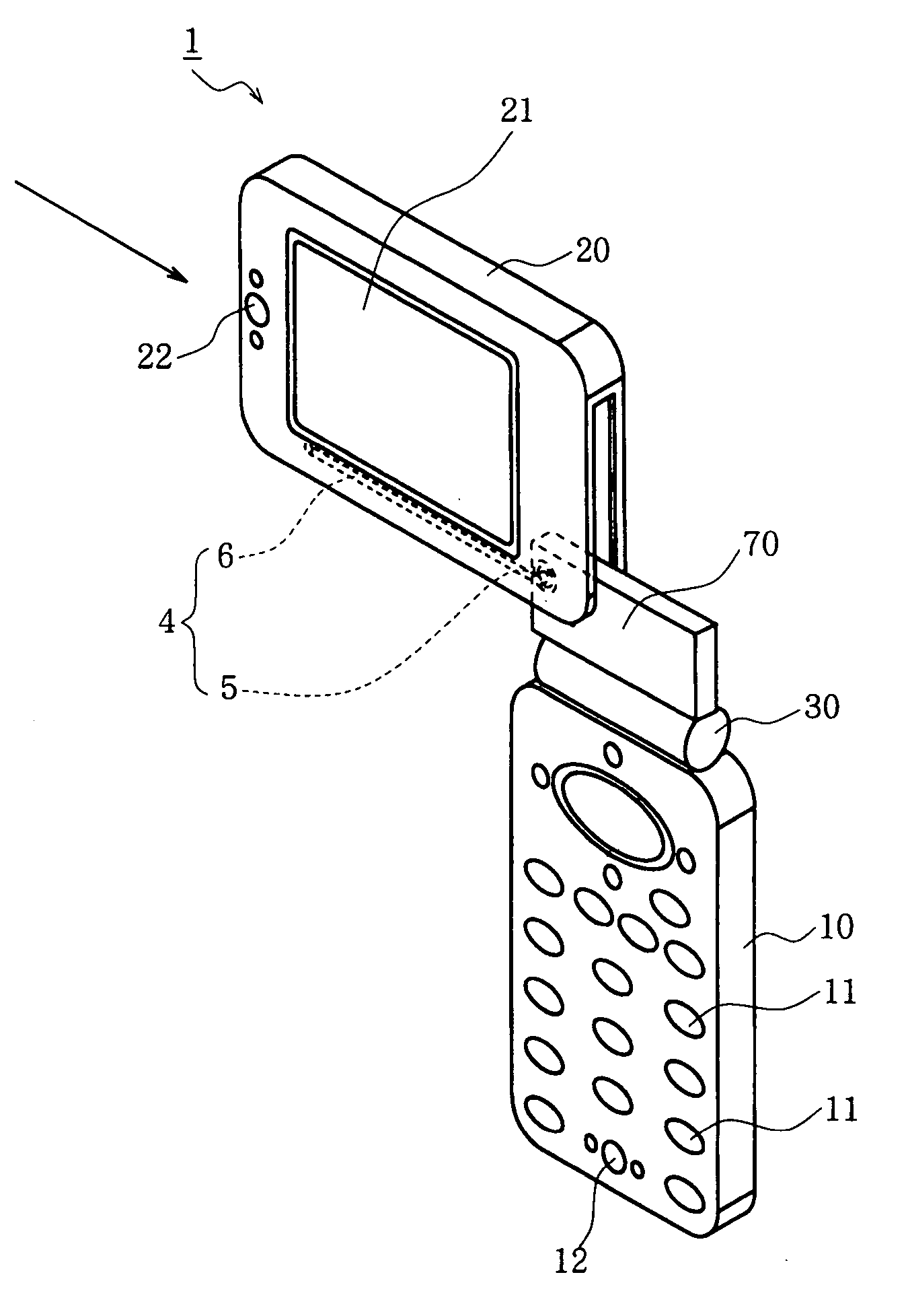
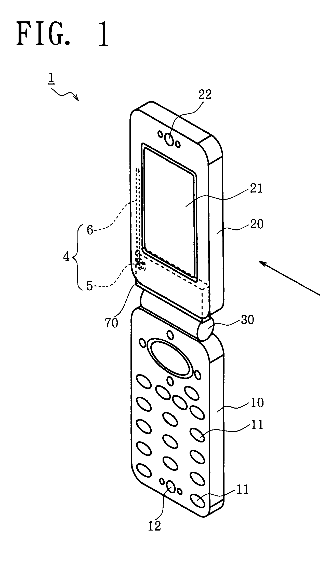
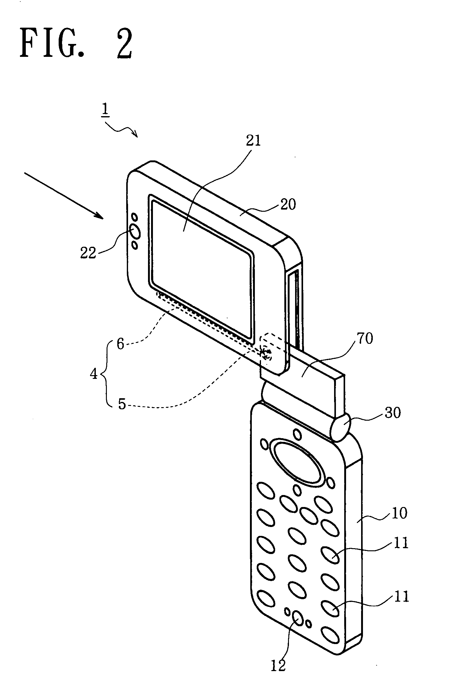
[0034]The foldable portable telephone of the present invention has a television broadcast receiving function and a wireless communications function. The telephone has a main body 1, which comprises a first case 10 vertically elongated as shown in FIG. 1, a second case 20 similarly vertically elongated, a hinge mechanism 30 for making the two cases 10, 20 closable or openable, and a connecting mechanism 4 for making the two cases 10, 20 rotatable and slidable relative to each other. The connecting mechanism 4 comprises a pivot mechanism 5 for rotating the second case 20 relative to the first case 10, and a slide mechanism 6 for slidingly moving the second case 20 relative to the first case 10. The lower end of the second case 20 is connected to the upper end of the first case 10 by the hinge mechanism 30 and the connecting mechanism 4, whereby the first case 10 and the second case 20 are closable toward or openable from each other by the action of the hinge mechanism 30.

[0035]The fir...

second embodiment

[0047]FIGS. 8 to 10 show a portable telephone of this embodiment, wherein a second case 20 is rotatable and slidable relative to the first case 10 by the same connecting mechanism 4 as in the first embodiment, whereas the main body 2 of this embodiment has no hinge mechanism. The first case 10 and the second case 20, both vertically elongated, are attached to each other only by the connecting mechanism 4.

[0048]Stated more specifically, a support plate 70 is attached to the upper end of the first case 10, and engaging pins 71, 71 projecting from the front side and rear side of the support plate 70 are slidably fitted in respective slide grooves 26, 26 between first bearing portions 24, 24 and second bearing portions 25, 25. The grooves 26, 26 are formed in the inner surfaces of the second case 20 which define a compartment 23 for accommodating the support plate. In this way, the same pivot mechanism 5 and slide mechanism 6 as in the first embodiment are provided.

[0049]In the course o...

third embodiment

[0050]FIGS. 11 to 14 show a portable telephone of this embodiment which has the same construction as the first embodiment except the construction for rotating and slidingly moving a second case 80 relative to a first case 10 by the action of a connecting mechanism 40. Accordingly, a description will be given only of the construction for rotating and slidingly moving the second case 80 by the action of the connecting mechanism 40. As to the other construction, like parts are designated by like reference numerals for the other construction and will not be described repeatedly.

[0051]With reference to FIG. 11, a support plate 72 has a front surface and a rear surface which are parallel to the surface of the second case 80 and is attached to the upper end of the first case 10. A pair of engaging pins 73, 73 in alignment with each other are elastically supported on and retractably attached to the front and rear sides of the support plate 72. The second case 80 is internally provided with ...


PUM


Abstract

A portable wireless terminal device which has a main body including a first case provided with a plurality of manual keys, a second case provided with a display having a rectangular screen of a predetermined aspect ratio, and a connecting mechanism for interconnecting the two cases. The connecting mechanism includes a pivot mechanism for rotating the second case relative to the first case along a plane parallel to the screen. For wireless communication, the display is activated in a screen position wherein the screen is elongated vertically. For receiving a television broadcast, the display is activated in a screen position wherein the screen is elongated horizontally.

Description

BACKGROUND OF THE INVENTION[0001]1. Field of the Invention[0002]The present invention relates to portable wireless terminal devices, such as portable telephones, which have a rectangular display screen.[0003]2. Description of the Related Art[0004]Portable telephones have made enormous progress in recent years as portable information processing terminal devices having not only a telephone communications function but also a mail function, an internet function and a camera function and adapted to process a wide variety of information. Efforts are recently made to develop portable telephones having a television broadcast receiving function (see, for example, JP-A No. 1999-215217).[0005]Common portable telephones have a vertically elongated case to ensure portability. The case has a receiver at the upper end of the front side thereof, a transmitter at the lower end of the front side, and a plurality of manual keys and a display in the region between the receiver and the transmitter. The ...

Claims


Application Information

Patent Timeline
IPC IPC(8): H04M1/00H04M1/02H04M1/72403H04N5/64H04W88/02
CPCH04N5/64H04M1/0235H04M1/0214H04M1/0227H04M1/0233H04M1/0237H04M1/72522H04M1/72403
Inventor MATSUNAMI, KANAKO
Owner KYOCERA CORP
Why Eureka
Eureka Blog
Learn More