Eureka AIR delivers breakthrough ideas for toughest innovation challenges, trusted by R&D personnel around the world.

Tape Measuring Device

a tape measuring and tape measure technology, applied in the field of tape measuring devices, can solve the problems of not providing highly accurate sighting of dimensions measured by pocket or hand-held tape measures, not retaining accurate measurements, and common precision and efficiency, so as to facilitate the transfer and marking of such measurements, facilitate the quick and easy manipulation of tape measures, and duplicate multiple pieces of work

Inactive Publication Date: 2017-11-02
M1 ENTERPRISES LLC
View PDF1 Cites 0 Cited by
  • Summary
  • Abstract
  • Description
  • Claims
  • Application Information

AI Technical Summary

Benefits of technology

The tape measuring device is a tool that improves the accuracy and replication of a measurement. It includes an indicator and marking assembly that helps in reading the measurements. The device has a mount that can be attached to a tape measure housing and a stop plate with flanges to assist in reading the markers on the tape. The device is small, easy to handle, and can be used with a standard pocket tape measure. It also has a design to prevent damage to the device. Overall, the invention solves problems of inaccurate human eyesight and memory, and it is efficient, effective, and useful for people with various limitations such as poor vision or motor skills.

Problems solved by technology

Precision and efficiency are common problems in reading, recording, transferring and marking of measurements.
Standard “pocket” or hand-held tape measures do not provide highly accurate sighting of the dimensions measured, do not retain the accurate measurement for transfer to another location or material piece of work, and do not include a tool to accurately scribe or mark the measurement immediately after transfer.
Also, currently known tape measuring devices are susceptible to breakage and damage due to inferior construction and design.

Method used


Image

  • Tape Measuring Device
  • Tape Measuring Device
  • Tape Measuring Device

Examples


Embodiment Construction

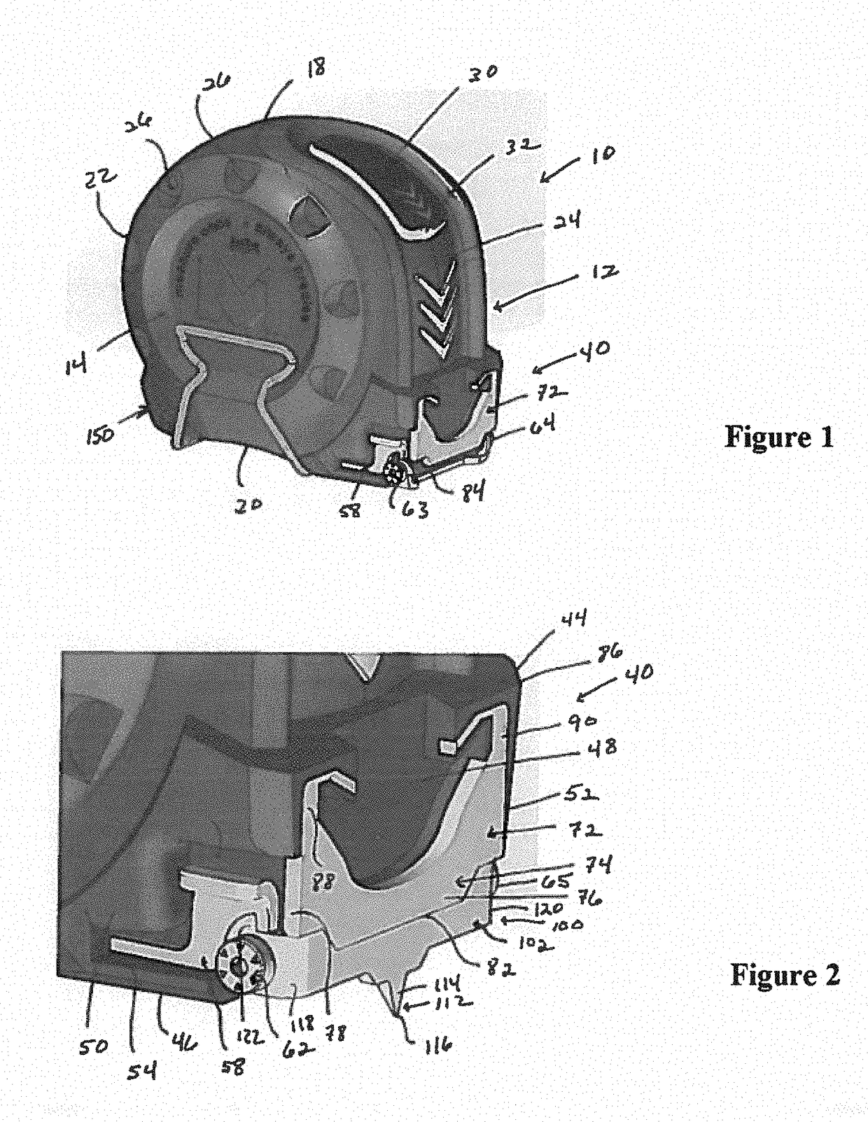
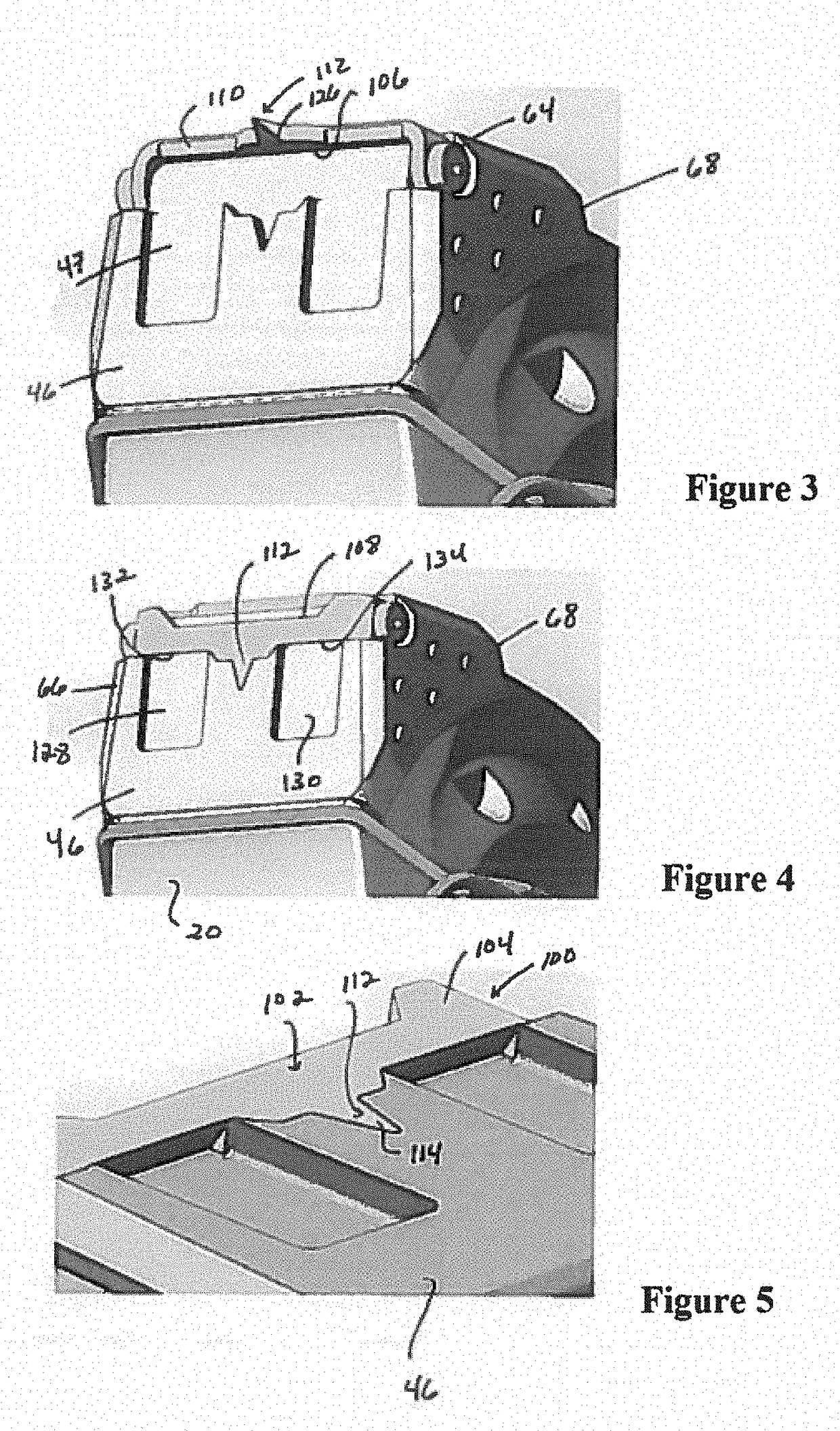
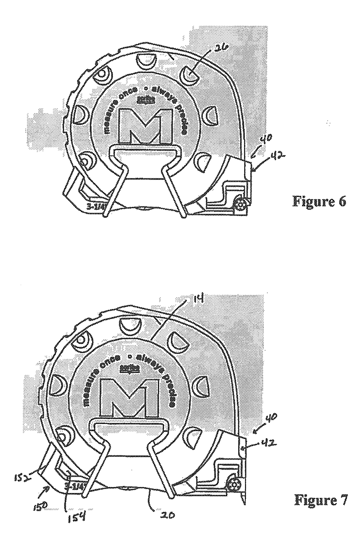
[0023]The improved tape measuring device of the present invention comprises an indicator and marking assembly comprising a mount, a stop plate, and a marker plate. The mount is specially configured to be integrally formed with or easily attached to a standard tape measure including, for example, a standard size / shape of “pocket” or hand-held tape measure, thereby enhancing normal usage and function of the tape measure. Alternatively, the mount may be integrally formed with or easily attached to an exemplary housing for a tape measure as shall be described herein. Each of the stop plate and the marker plate is configured and positioned relative to one another on the mount to provide a reliable way of measuring, tracking, and replicating a measurement. More particularly, the stop element provides a means whereby a tape blade of the tape measuring device, may be stabilized temporarily without the necessity of implementing a locking mechanism such as is typically found in conventional t...


PUM


Abstract

A tape measuring device comprising a mount which is integrally formed with or attached to a housing. A specially designed stop plate is disposed on the mount. The stop plate provides a means whereby the indicia located on a tape blade of the tape measuring device may be easily located and read. The stop plate further provides a means for the precise taking and replication of a measurement. The tape measuring device further comprises a marker plate. The marker plate comprises a scribe which can mark an object to be measured. The marker plate is pivotally attached to the mount to allow for the retraction of the scribe when the marker plate is not in use, and for expansion of the scribe when the marker plate is in use.

Description

BACKGROUND TO THE INVENTION1. Field of the Invention[0001]The present invention relates to measuring devices, and more particularly, to a device for measuring, reading, transferring, and marking a measurement to be marked on a piece of work or material.2. Background of the Invention[0002]Precision and efficiency are common problems in reading, recording, transferring and marking of measurements. Standard “pocket” or hand-held tape measures do not provide highly accurate sighting of the dimensions measured, do not retain the accurate measurement for transfer to another location or material piece of work, and do not include a tool to accurately scribe or mark the measurement immediately after transfer. Also, currently known tape measuring devices are susceptible to breakage and damage due to inferior construction and design.SUMMARY OF THE INVENTION[0003]The above-mentioned problems of the prior art are overcome or eliminated by a measuring and marking device for use in the precise tak...

Claims


Application Information

Patent Timeline
Patent Type & Authority Applications(United States)
IPC IPC(8): G01B3/10
CPCG01B2003/1089G01B3/1084G01B3/1056G01B3/1061G01B3/1089
Inventor PERI, ODED
Owner M1 ENTERPRISES LLC
Why Eureka
Eureka Blog
Learn More