Floor structure of vehicle body

a technology of vehicle body and floor structure, which is applied in the direction of roofs, transportation and packaging, vehicle arrangements, etc., can solve the problems of easy deformation at the joint part, ineffective propagation of collision load f inputted into the side sill due to a side collision, and easy deformation at the narrow portion of the lateral, so as to reduce the weight of the vehicle, effectively propagate to the cross members, and strengthen rigidity against external forces

Inactive Publication Date: 2007-03-27
HONDA MOTOR CO LTD
View PDF19 Cites 43 Cited by
  • Summary
  • Abstract
  • Description
  • Claims
  • Application Information

AI Technical Summary

Benefits of technology

[0015]According to the floor structure of the vehicle body of the present invention, it is possible to enhance rigidity against an external force from a side of a vehicle, and to allow a side collision onto a side sill to effectively propagate to cross members. Accordingly, reinforcement members provided on the side sills and the like can be omitted, resulting in reducing the weight of the vehicle.

Problems solved by technology

Consequently, the conventional floor structure has a disadvantage that deformation easily occurs at the narrow portion of the lateral beads 32 when the collision load F is inputted from the side of the vehicle.
Hence, the collision load F inputted into the side sill due to a side collision cannot propagate effectively to the cross members.
Consequently, the conventional floor structure of the vehicle body has another disadvantage that deformation can easily occur at the joint part between the side sill and the cross member.
However, this solution increases weight of the vehicle body and may decrease the fuel economy.

Method used


Image

  • Floor structure of vehicle body
  • Floor structure of vehicle body
  • Floor structure of vehicle body

Examples


first embodiment

[0029]With reference to drawings, explanations will be given on a floor structure of a vehicle body according to a first embodiment of the present invention.

[0030]Note that rear and front directions (or a longitudinal direction), and right and left directions (or a lateral direction) used in the explanation are based on a condition in which a floor panel that is a principle component of the floor structure of the vehicle body is provided with a pair of right and left side sills and a pair of rear and front cross members, both of which constitutes the vehicle body. These directions are based on a driver's view direction, as well.

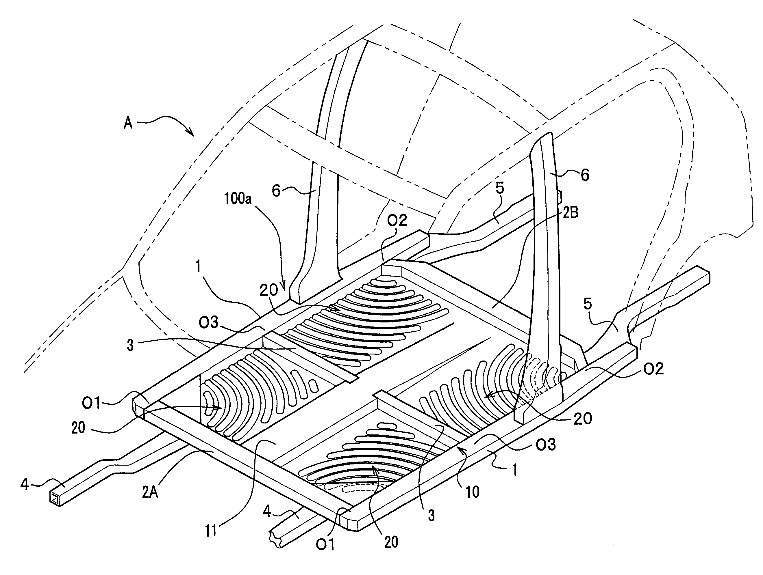
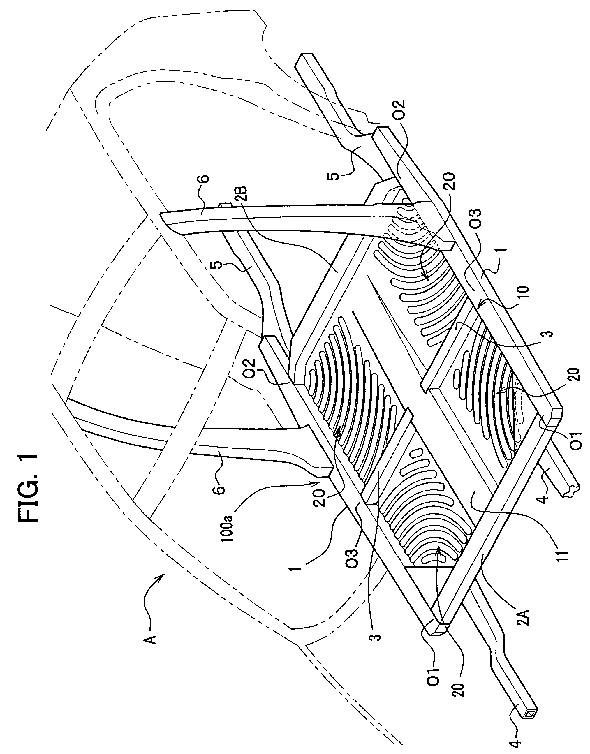
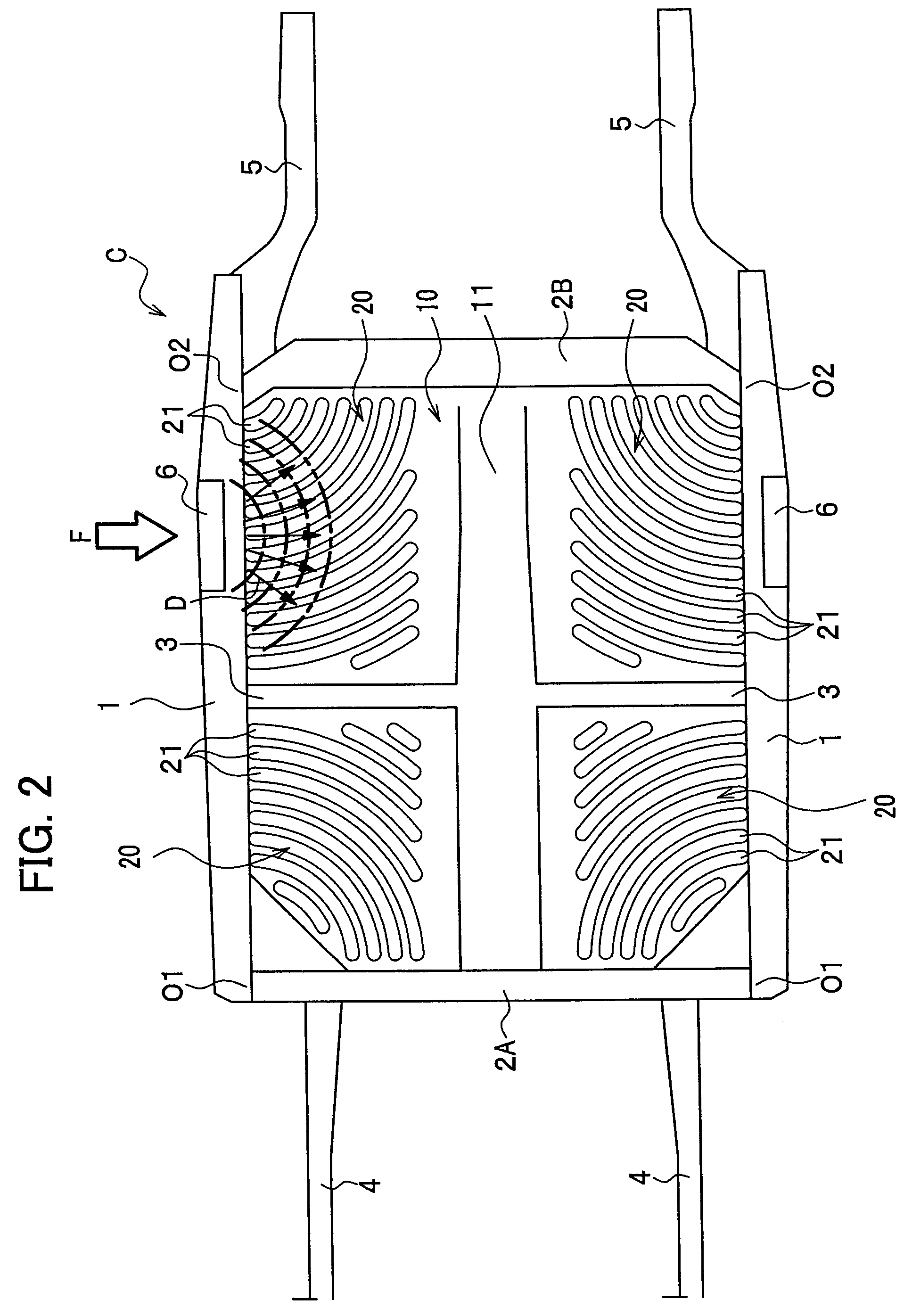
[0031]FIG. 1 is a perspective view of a vehicle body structure around a vehicle compartment to explain details of the floor structure of the vehicle body according to the first embodiment. FIG. 2 is a plan view showing principle components of the vehicle body.

[0032]As shown in FIG. 1 the floor structure of the vehicle body 100a includes a pair of right and le...

second embodiment

[0054]With reference to drawings, explanations will be given on a floor structure of a vehicle body according to a second embodiment.

[0055]Note that, in the explanations on the second embodiment, the same components of the second embodiment as those of the first embodiment are denoted by the same numeral references of the first embodiment.

[0056]FIG. 7 is a general perspective view showing the floor structure of a vehicle body 100b according to the second embodiment. FIGS. 8A and 8B are partially enlarged perspective views. FIG. 8A is a right front side of the floor structure of the vehicle body 100b, and FIG. 8B is a left front side thereof. As in the first embodiment, rear and front directions (or longitudinal direction), and right and left directions (or lateral direction) used in the explanation in the second embodiment are based on a condition in which a floor panel 10 that is a principle component of the floor structure of the vehicle body is provided with a pair of right and l...


PUM


Abstract

A floor structure of a vehicle body capable of enhancing rigidity against a external force from a side of the vehicle body includes a pair of right and left side sills, a pair of front and rear cross members provided between the pair of right and left side sills, and a floor panel surrounded by the pair of right and left side sills and the pair of front and rear cross members. The floor panel is provided thereover with beads in a concentric arc shape spreading from parts at which the side sills and the cross members are vertically joined to each other. Reinforcement members are provided at corners defined by the side sills and the cross members in such a manner that the reinforcement members are slantingly placed and joined to the side sills and cross members.

Description

CROSS-REFERENCE TO RELATED APPLICATIONS[0001]This application claims the benefit of Japanese Patent Application No. 2005-117951 filed on Apr. 15, 2005 and Japanese Patent Application No. 2005-120520 filed on Apr. 19, 2005, the disclosures of which are incorporated herein by reference.BACKGROUND OF THE INVENTION[0002]1. Field of the Invention[0003]The present invention relates to a floor structure of a vehicle body for a motor vehicle and the like, particularly to a floor structure of a vehicle body to appropriately distribute a side collision load.[0004]2. Description of the Related Art[0005]A technique has been known as disclosed, for example, in JP-A-H06-107234 as a conventional technique for enhancing rigidity of a floor of a floor structure of a vehicle body including a floor panel for a motor vehicle and the like.[0006]In the floor structure of the vehicle body according to the invention disclosed in JP-A-H06-107234, a floor panel 30, as shown in FIG. 11, has a structure includ...

Claims


Application Information

Patent Timeline
Patent Type & Authority Patents(United States)
IPC IPC(8): B62D25/20
CPCB62D21/157B62D25/2036B62D25/20B62D25/025
Inventor EGAWA, YASUHISAYASUHARA, SHIGETOSATO, TOSHIAKIKUDOH, AKIHISA
Owner HONDA MOTOR CO LTD
Why Eureka
Try Eureka