Ink jet nozzle assembly with a thermal bend actuator

a thermal actuator and actuator technology, applied in the field of microelectromechanical devices, can solve the problems of bending and bending stresses being set up in the thermal actuator, uneven expansion of materials, and bending of the laminated structure upon cooling, and achieve the effect of the same thermal expansion and elasticity characteristics

Inactive Publication Date: 2007-03-27
ZAMTEC +1
View PDF74 Cites 62 Cited by
  • Summary
  • Abstract
  • Description
  • Claims
  • Application Information

AI Technical Summary

Benefits of technology

[0010]an elongate actuator that is fast with the substrate at a fixed end, the elongate actuator having a laminated structure of at least one inner layer and a pair of opposed, outer layers, the outer layers having substantially the same thermal expansion and elasticity characteristics, with one of the outer layers defining an electrical heating circuit that is in electrical contact with the drive circuitry to be heated and to expand on receipt of an electrical signal from the drive circuitry and to cool and contract on termination of the signal, thereby to generate reciprocal movement of the actuator.

Problems solved by technology

Many of the thermal actuators use a combination of materials and a bending action which results from an uneven expansion of the materials.
A significant problem with such actuators is that the different materials can result in bending and bending stresses being set up in the thermal actuator when the thermal actuator is inoperative and exposed to transient conditions.
The fact that the materials have different thermal expansion characteristics can result in the bending of the laminated structure upon cooling.
Those skilled in the field of micro electromechanical systems fabrication will appreciate that this is highly undesirable.

Method used


Image

  • Ink jet nozzle assembly with a thermal bend actuator
  • Ink jet nozzle assembly with a thermal bend actuator
  • Ink jet nozzle assembly with a thermal bend actuator

Examples


Embodiment Construction

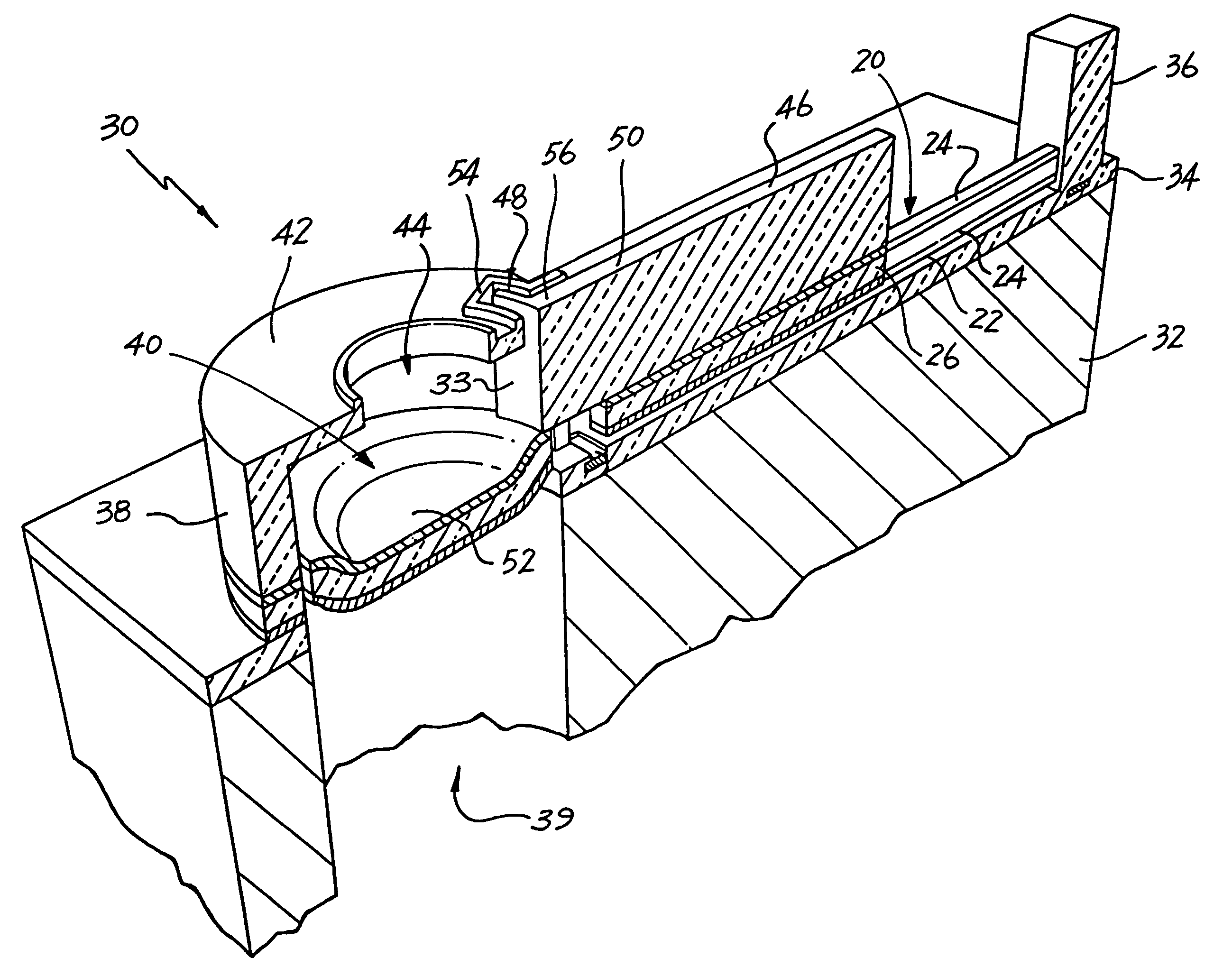
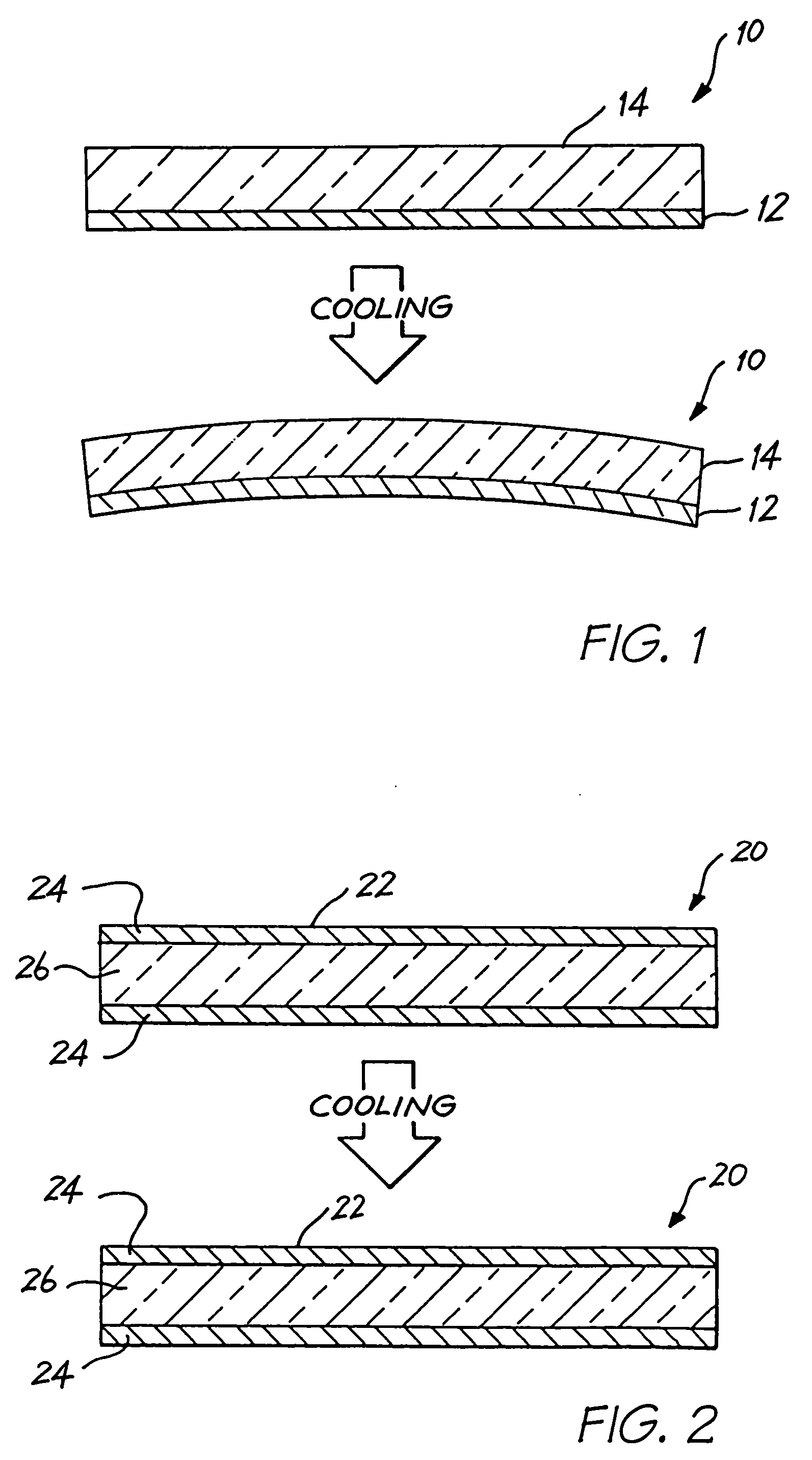
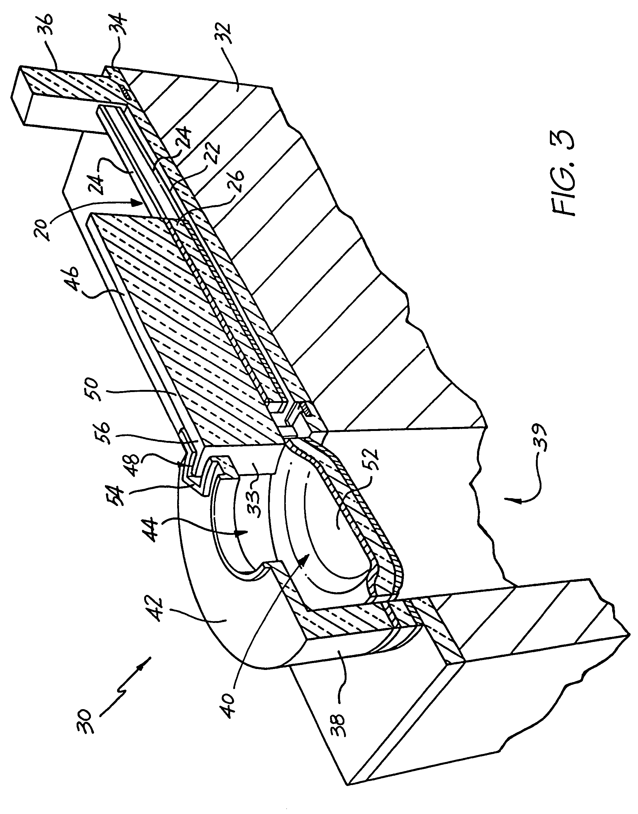
[0029]In FIG. 1, reference numeral 10 generally indicates an actuating mechanism in the form of a bi-layer thermal bend actuator.

[0030]As set out above, the device in which the thermal bend actuator 10 is to be incorporated is formed as part of an integrated circuit fabrication process. It follows that the thermal actuator 10 is manufactured in a deposition and etching process. Thus, once a first layer 12 has been deposited and prepared, a second layer 14 is deposited on the first layer 12. In order to operate correctly, one of the layers, in this case the first layer 14 is of a material having a higher coefficient of thermal expansion than the material of the second layer 12.

[0031]As is well known in the field of integrated circuit fabrication, deposition of material occurs at a temperature which is, of necessity, significantly higher than ambient temperature. This results in a heating of the first layer 12 and the deposited second layer 14.

[0032]Also, in order to operate, the laye...


PUM


Abstract

An ink jet nozzle assembly for an inkjet printer includes a wafer substrate defining an ink supply passage. A drive circuitry layer is formed on the wafer substrate. A nozzle is formed on the drive circuitry layer and defines an ink chamber in fluid communication with the ink supply passage, a side aperture in fluid communication with the ink chamber and an ink ejection port in fluid communication with the ink chamber. A support extends from the drive circuitry layer. A thermal bend actuator extends from the support, through the side aperture and terminates in a free end within the ink chamber. The actuator includes a first layer having a first co-efficient of thermal expansion, and a second layer deposited on the first layer which has a second co-efficient of thermal expansion. The first layer is coupled to the drive circuitry layer so that, in use, the drive circuitry layer can actuate bending of the thermal bend actuator so as to move the free end and thereby eject ink from the ink ejection port.

Description

CROSS REFERENCES TO RELATED APPLICATIONS[0001]The present application is a Continuation of U.S. application Ser. No. 11 / 185,721 filed on Jul. 21, 2005, now issued as U.S. Pat. No. 7,083,263, which is a Continuation of U.S. application Ser. No. 10 / 713,084 filed on Nov. 17, 2003, now issued as U.S. Pat. No. 7,066,574, which is a Continuation of U.S. application Ser. No. 10 / 401,987 filed on Mar. 31, 2003, now issued as U.S. Pat. No. 6,663,225, which is a Continuation of U.S. application Ser. No. 09 / 864,332 filed on May 25, 2001, now issued as U.S. Pat. No. 6,540,331, which is a Continuation-in-part of U.S. application Ser. No. 09 / 112,767 filed on Jul. 10, 1998, now issued as U.S. Pat. No. 6,416,167, the entire contents of which are herein incorporated by reference.[0002]U.S. application Ser. No. 09 / 864,332 filed on May 25, 2001, now granted U.S. Pat. No. 6,540,331, 09 / 112,767 filed on Jul. 10, 1998, now granted U.S. Pat. No. 6,416,167 and 09 / 112,768 filed on July 10, 1998, now granted ...

Claims


Application Information

Patent Timeline
Patent Type & Authority Patents(United States)
IPC IPC(8): B41J2/04B41J2/05B41J2/14B41J2/16B41J2/165B41J2/175B41J3/42B41J3/44B41J11/00B41J11/70B41J15/04G06F1/16G06K1/12G06K7/14G06K19/06G06K19/073G07F7/08G07F7/12G11C11/56H04N1/00H04N1/21H04N1/32H04N5/225H04N5/262
CPCB41J2/14427B41J2/1623B41J2/1626B41J2/1628B41J2/1629B41J2/1631B41J2/1632B41J2/1635B41J2/1637B41J2/1639B41J2/1642B41J2/1643B41J2/1645B41J2/1646B41J2/1648B41J2/17513B41J2/17596B41J3/445B41J11/0005B41J11/70B41J15/04B82Y30/00G06K1/121G06K7/14G06K7/1417G06K19/06037G11C11/56H04N1/2154H04N5/225H04N5/2628B41J2/1601H04N2101/00B41J2/16585B41J2002/041B41J2202/21B42D2035/34H04N23/00
Inventor SILVERBROOK, KIA
Owner ZAMTEC
Why Eureka
Try Eureka