Static mixer and a method of manufacture thereof

a technology of static mixer and mixer head, which is applied in the direction of clay mixing apparatus, mixing/kneading with horizontally mounted tools, transportation and packaging, etc. it can solve the problems of inability to achieve uniform distribution of acetaldehyde (aa), a thermal degradation product of pet, and uneven distribution of acetaldehyde, so as to avoid weaknesses, eliminate tangential stress and outward radial pulling forces, and avoid excessive localized stress

Active Publication Date: 2007-04-03
HUSKY INJECTION MOLDING SYST LTD
View PDF43 Cites 60 Cited by
  • Summary
  • Abstract
  • Description
  • Claims
  • Application Information

AI Technical Summary

Benefits of technology

The patent text describes the use of static mixers in multi-cavity preform molding systems, such as PET systems. The technical effect of using static mixers is to provide a more uniform distribution of AA in the melt stream, which results in consistent levels of AA in the preforms. However, there are various types of static mixers with different configurations and methods of manufacture, which can lead to structural failure and undesired taste in the beverage bottles. The technical effect of the patent is to provide a new design for a static mixer that overcomes these issues and provides a more reliable and cost-effective solution for the production of preforms.

Problems solved by technology

The technical problem addressed in this patent text is the need for a static mixer that can effectively mix and withstand the high operational pressures of a plastic injection molding system. Existing static mixers have limitations in terms of mixing efficiency and cost, and often require a complete refurbishment of the tool and lost production when used in a new system. The patent aims to provide a more cost-effective and reliable solution for incorporating a static mixer into existing plastic injection molding systems.

Method used


Image

  • Static mixer and a method of manufacture thereof
  • Static mixer and a method of manufacture thereof
  • Static mixer and a method of manufacture thereof

Examples


Embodiment Construction

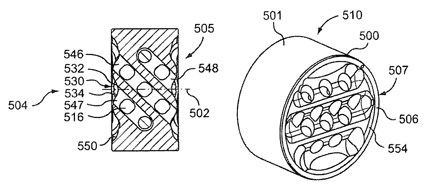
[0039]FIG. 3 illustrates a static mixer 110 according to a simplified conceptual embodiment of the invention. The static mixer 110 comprises a mixer body 100 with a first and a second mutually inclined and interconnected passageways 112 and 114 formed therein that extend between flow faces 104 located at opposite ends of the mixer body 100. A potion of the passageways intersect with overlapping boundaries at a mixing portal 116 to provide a convoluted flow path between, the flow faces 104. In operation, the static mixer 110 is arranged in a fluid flow channel (not shown) wherein a fluid flow interacts with a first mixer flow face 104 and a fluid flow is established through inlet fluid portals 118 of the passageways that are arranged on the flow face 104; the fluid then passes down through the first and second passageway 112 and 114 as first and second flow fields respectively, as represented by the flow lines. The first and second flow fields then encounter the mixing portal 116, wh...


PUM

PropertyMeasurementUnit
Angleaaaaaaaaaa
Angleaaaaaaaaaa
Angleaaaaaaaaaa

Abstract

A static mixer comprising a mixer body with a first and a second array of intermeshed and interconnecting passageways formed therein that connect, and provide a convoluted flow path between, flow faces at ends of the mixer body. The first and second arrays of passageways preferably interconnect such that the boundaries of adjacent intermeshed passageways overlap to form mixing portals. When used in an injection molding system, a singular melt flow is initially divided at the first flow face of the static mixer, wherein the melt flow divides into the intermeshing passageways and further divides and re-combines at the locations of mixing portals before exiting the static mixer at the second flow face as homogenized melt.

Description


Claims


Application Information

Patent Timeline
Owner HUSKY INJECTION MOLDING SYST LTD
Why Eureka
Try Eureka