Active camouflage using real-time spectral matching

a camouflage and real-time technology, applied in the field of camouflage techniques, can solve the problems of only required military camouflage, traditional camouflage techniques suffer from a number of basic defects, and traditional camouflage is not adaptable to changes in the surroundings

Active Publication Date: 2007-04-03
THE BOEING CO
View PDF10 Cites 14 Cited by
  • Summary
  • Abstract
  • Description
  • Claims
  • Application Information

AI Technical Summary

Problems solved by technology

As a result, military camouflage was only required to provide a good match over the narrow segment of the electromagnetic spectrum visible to the human eye.
However, traditional camouflage techniques suffer from a number of basic defects.
First, traditional camouflage is not adaptable to changes in the surroundings, requiring a different type of traditional camouflage for each different type of background.
Second, traditional camouflage is passive in nature.
Consequently, changes in conditions such as angle or amount of illumination may make the camouflage far less effective.
Third, the reflective spectrum of traditional camouflage generally is not a good match to the surroundings.
None of these approaches resolves the fundamental problems cited above, however.
That is, all of these approaches require a different camouflage for different backgrounds; are not active in nature; and are still unlikely to provide a tight enough spectral match to fool multispectral or hyperspectral remote-sensing instruments.
Unfortunately, the spectral signature must be constructed out of the limited palette of reflective surfaces that are built into the camouflage system.
Finally, the approach is limited to the range of light energy readily transmitted by fiber optics; many of the devices used to detect camouflaged objects operate outside this wavelength range.
Moreover, the Schowengerdt reference concedes that it is designed to operate in the visible light spectrum, and would therefore not provide concealment from standard military remote sensing instruments (or radar).

Method used


Image

  • Active camouflage using real-time spectral matching
  • Active camouflage using real-time spectral matching
  • Active camouflage using real-time spectral matching

Examples


Embodiment Construction

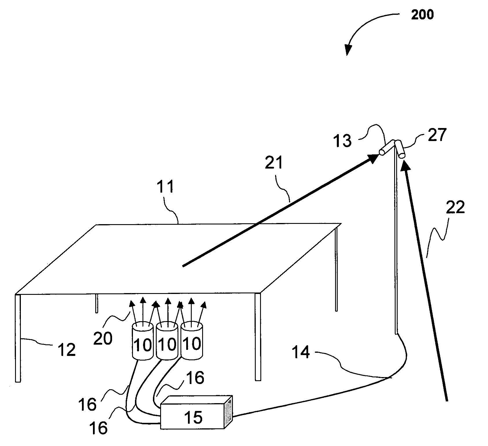
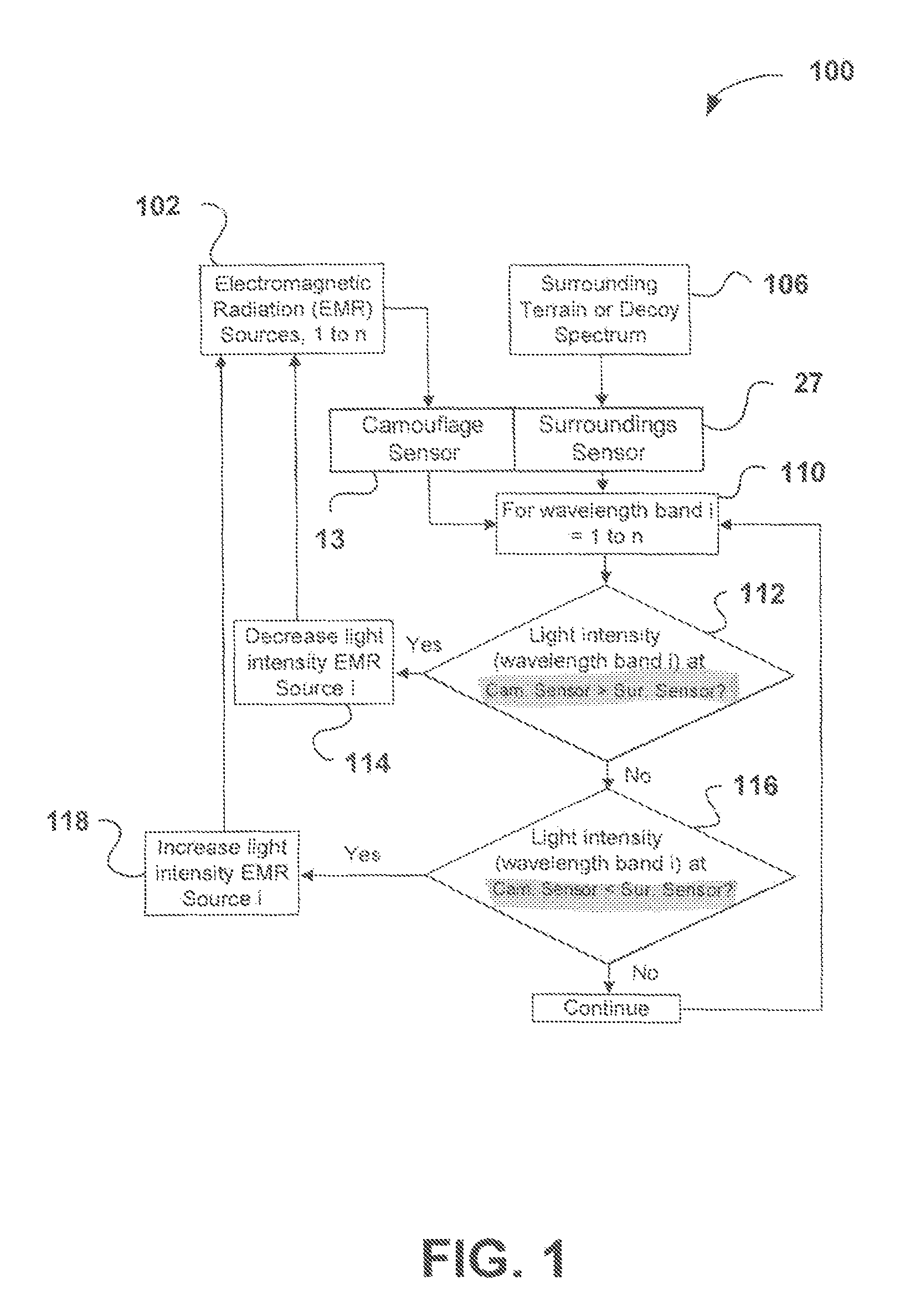
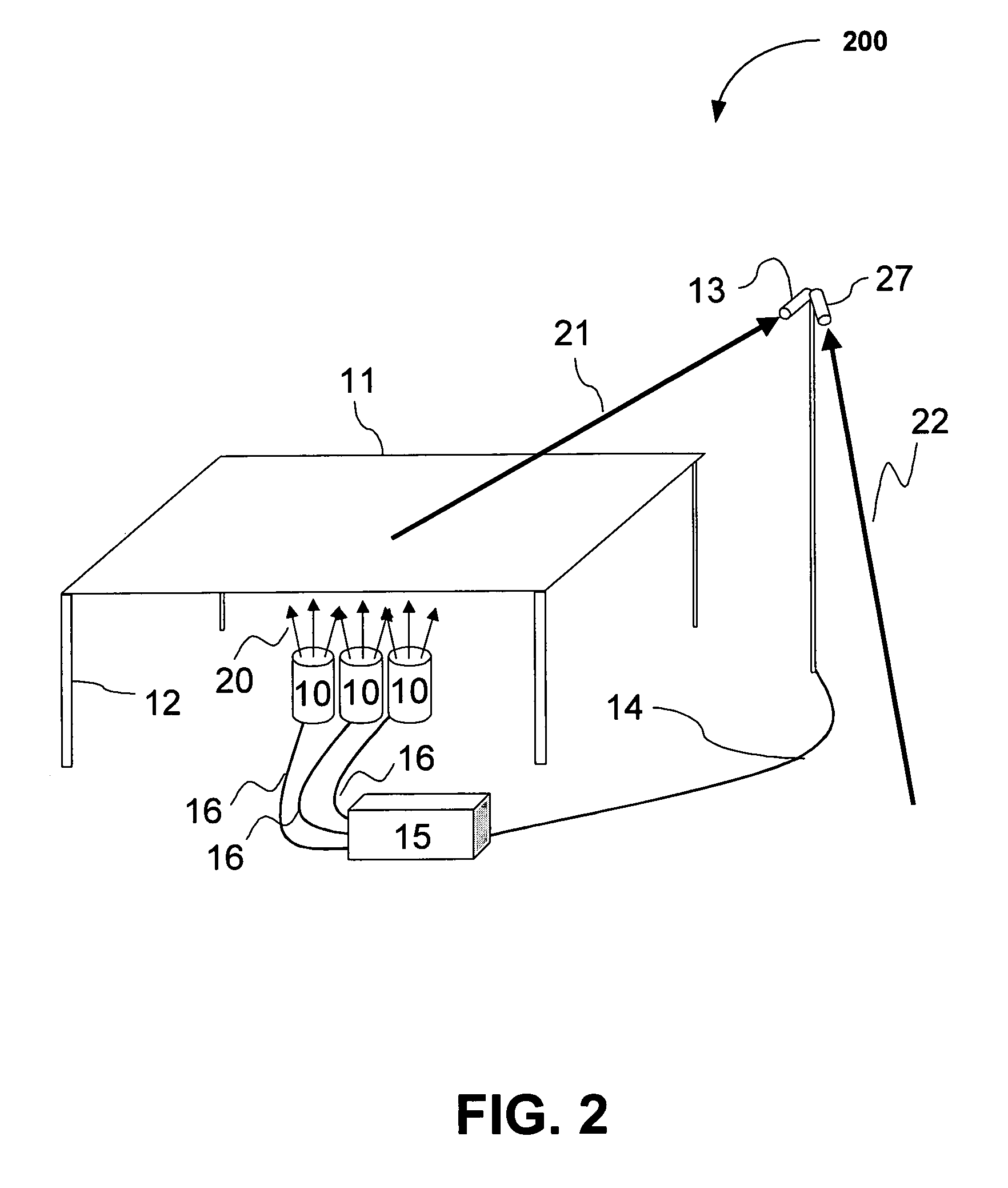
[0022]An invention is disclosed for an active camouflage system that is adaptable to changes in the surroundings, including changes in the background, and changes in the illumination conditions. Further, embodiments of the present invention provide a camouflage process that is adaptive across a broad spectral range, beyond the range of the human eye. As a result, embodiments of the present invention provide an “active” camouflage process that is capable of detailed spectral matching to the surroundings and adapts instantly to new surroundings by changing the observed spectrum of the camouflage automatically in response to changes in the surroundings. Moreover, embodiments of the present invention provide a camouflage process that is capable of detailed spectral matching to the surroundings across a wide wavelength range that can interfere with detection by modern multispectral and hyperspectral sensors.

[0023]In the following description, numerous specific details are set forth in or...


PUM


Abstract

An invention is provided for concealing an object. The invention includes a plurality of electromagnetic radiation sources that generate an electromagnetic radiation spectrum, and a controller in communication with the plurality of electromagnetic radiation sources. The controller includes logic that compares the electromagnetic radiation spectrum generated from the plurality of electromagnetic radiation sources with an electromagnetic radiation spectrum from an environment surrounding the object. In operation, the controller adjusts the plurality of electromagnetic radiation sources to generate an electromagnetic radiation spectrum that matches the electromagnetic radiation spectrum of the environment surrounding the object.

Description

BACKGROUND OF THE INVENTION[0001]1. Field of the Invention[0002]This invention relates generally to camouflage techniques, and more particularly to real time active spectral matching camouflage.[0003]2. Description of the Related Art[0004]Camouflage is a technique for concealment, which involves disguising an object, in plain sight, in order to hide it from something or someone. Historically, camouflage has been designed to match colors, contours, and / or patterns of the camouflage to a background. For example, in times of conflict soldiers often wear special camouflage clothing to become less visible. Such camouflage may be placed between the viewer and the concealed object, or may be applied directly to the object itself.[0005]Another type of camouflage is the creation of decoys. Most camouflage is designed to make an object appear to blend with its surroundings. In the case of decoys, the purpose of the camouflage is not to make the object “disappear” into the surroundings, but in...

Claims


Application Information

Patent Timeline
Patent Type & Authority Patents(United States)
IPC IPC(8): G01J1/32A63G31/00A63J5/02
CPCA63J21/00F41H3/00G01J3/46G01J3/463
Inventor BLAKE, PAMELA L.
Owner THE BOEING CO
Why Eureka
Try Eureka