Construction of an interference matrix for a coded signal processing engine

a signal processing engine and interference matrix technology, applied in the field of methods and apparatuses, can solve the problems of complex receivers, interference from other sources, and complexity, and achieve the effect of facilitating acquisition, tracking and demodulation of signals

Active Publication Date: 2007-04-03
III HLDG 1
View PDF64 Cites 24 Cited by
  • Summary
  • Abstract
  • Description
  • Claims
  • Application Information

AI Technical Summary

Benefits of technology

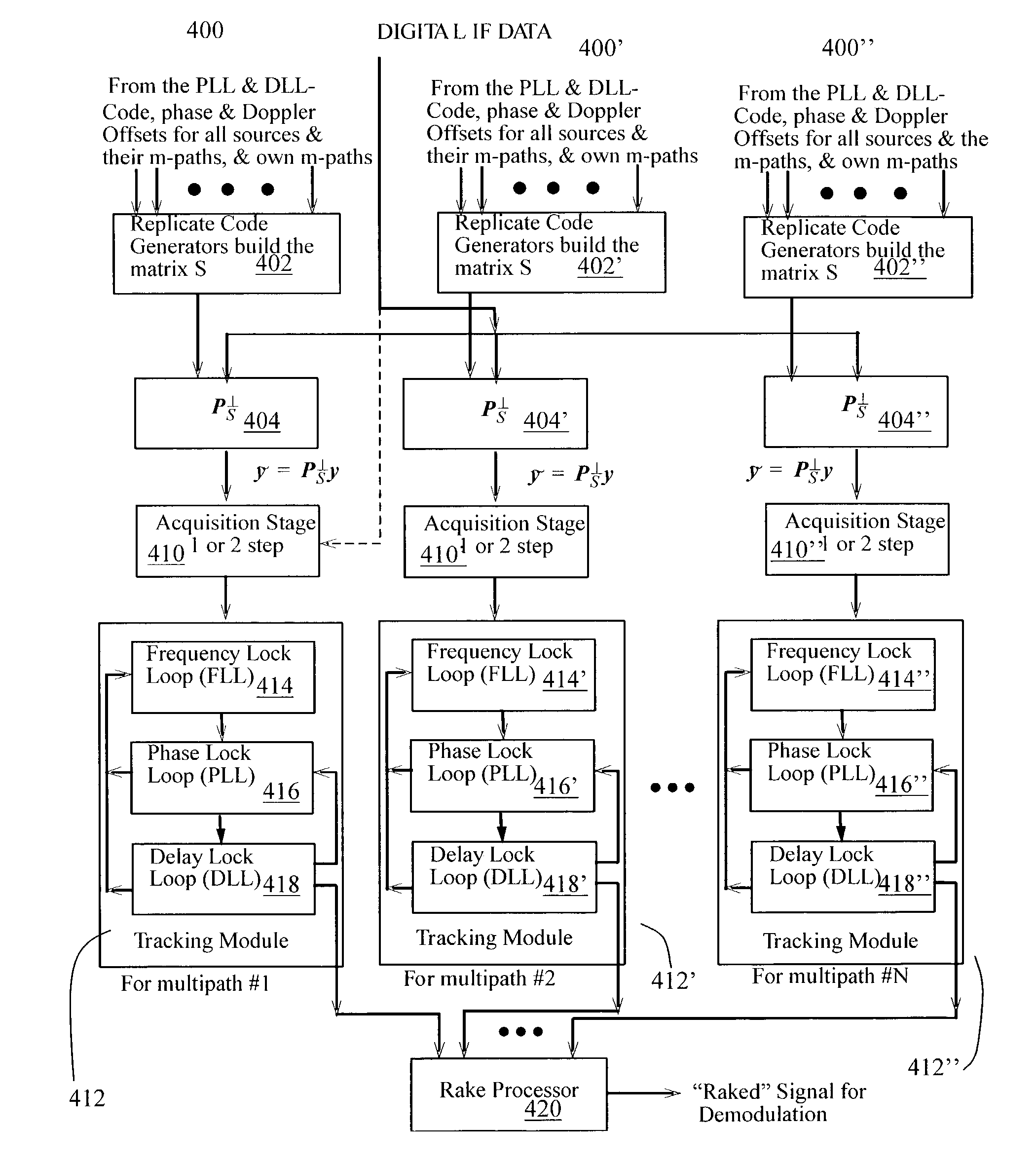
[0042]It is therefore an object of the present invention to provide a method for constructing an interference matrix S to provide interference mitigation through its use in a coded signal-processing engine (CSPE) to facilitate acquisition, tracking and demodulation of the signal of interest.
[0054]According to one broad aspect of the present invention, there is provided a method for constructing an interference matrix S. The interference matrix, used by the CSPE module in the receiver architecture, may mitigate interference and provide better acquisition, tracking and demodulation of coded signals based on signal to noise ration (SNR) or bit error rate (BER). Furthermore, it may provide for the acquisition, tracking and demodulation of coded signals that were previously concealed by interference.

Problems solved by technology

However, such receivers are more complex than receivers that distinguish between messages by time and / or frequency alone.
Complexity arises because the signal received is a linear combination of all the coded signals present in the spectrum of interest at any given time.
The signals from the other sources may be considered to be interference.
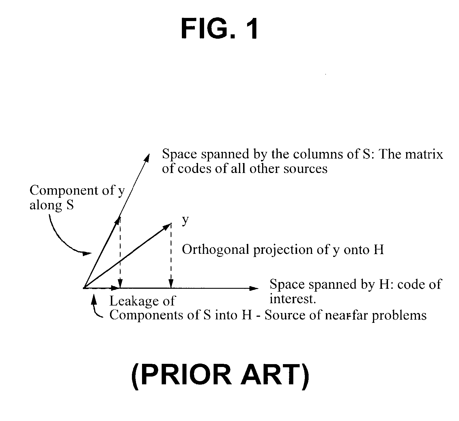
As the amplitudes of the other sources with non-orthogonal codes increase, the term (HTH)−1HTSφ contributes a significant amount to the correlation, which interferes with the detection of θ.
The first kind of interference results from one source's signals bleeding into the acquisition and tracking channels of another source.
The second type of interference occurs when one or more signals, e.g, a line-of-sight and / or multipath signal, interfere with the ability to acquire a second, third or fourth multipath signal from the same source.

Method used


Image

  • Construction of an interference matrix for a coded signal processing engine
  • Construction of an interference matrix for a coded signal processing engine
  • Construction of an interference matrix for a coded signal processing engine

Examples


example 1

[0264]This example is of a telecommunications embodiment of the construction of the S matrix and issues involved with the formation of S. These issues are discussed in detail in the following sub-sections.

[0265]In the case of wireless communication in the forward link, it is assumed that the mobile does not have any prior knowledge about which channels are active other than the pilot, paging and synchronization channels. Moreover, it does not have any prior knowledge of the relative powers of the various channels including the traffic channels. Specifically in CDMAOne (see IS-95), one could cancel all 64 channels (for complete cancellation of a base station) or a subset of the channels at the appropriate code, Doppler and phase offsets estimated from the pilot channel. The following discussion pertains directly to IS-95, but with some changes, e.g., the addition of QOF codes, supplementary channels and QPSK modulation, it would be possible to easily extend this telecommunications em...


PUM


Abstract

A novel method for generating an interference matrix S is disclosed. The method comprises the following steps: A) Determining the number of active channels N in a transmitter; B) Selecting the transmitter to be canceled and assigning the transmitters sequentially to the variable t; C) Selecting the channel to be cancelled and assigning the channels sequentially to the variable n, where n is less than or equal to N; D) Determining if a multipath signal should be canceled and assigning the multipaths of interest to the respective variable M; E) Generating a sequence of column vectors V; F) Repeating steps B, C, D, E, F and G for each column vector of interest; and G) Defining the S matrix as S=[V1 V2 . . . Vc] wherein the index denotes the column index c. In addition, an apparatus for generating the interference matrix is also disclosed.

Description

CROSS-REFERENCE TO RELATED APPLICATIONS[0001]This application makes reference to: U.S. Provisional Patent Application No. 60 / 422,476, entitled “Alternate Correlator Design for Coded Signal Processing Engine,” filed Oct. 31, 2002; U.S. Provisional Patent Application No. 60 / 421,565, entitled “A Projection Based Receiver for WCDMA Systems,” filed Oct. 28, 2002; U.S. Provisional Patent Application No. 60 / 418,181, entitled “Interference Suppression with Efficient Matrix Inversion in a DS-CDMA System,” filed Oct. 15, 2002; U.S. Provisional Patent Application No. 60 / 418,188, entitled “Carrier Phase Recovery Circuit,” filed Oct. 15, 2002; U.S. Provisional Patent Application No. 60 / 418,187, entitled “Method for Channel Amplitude Estimation and Interference Vector Construction,” filed Oct. 15, 2002; U.S. Provisional Patent Application No. 60 / 412,550, entitled “A Controller for Interference Cancellation in Spread Spectrum Systems,” filed Sep. 23, 2002; U.S. Provisional Patent Application No. 6...

Claims


Application Information

Patent Timeline
Patent Type & Authority Patents(United States)
IPC IPC(8): H04B15/00H04B1/10H04B1/707H04B1/7105H04B1/7107H04B1/7117H04B7/26
CPCH04B1/7105H04B1/7107H04B1/7117
Inventor OLSON, ERIC S.THOMAS, JOHN K.
Owner III HLDG 1
Why Eureka
Try Eureka