Self-centering unit

a self-centering and unit technology, applied in the field of self-centering units, can solve problems such as risk of damag

Inactive Publication Date: 2007-04-10
NEXION SPA
View PDF7 Cites 19 Cited by
  • Summary
  • Abstract
  • Description
  • Claims
  • Application Information

AI Technical Summary

Problems solved by technology

A first drawback is the need to individually move each head relative to the slide to adapt the self-centering unit to large-dimension wheel rims.
This operation is lengthy and laborious, the operator often forgetting to move a head, with the result that when the wheel rim is gripped by the heads it is not in the correct working position and risks undergoing damage.

Method used


Image

  • Self-centering unit
  • Self-centering unit
  • Self-centering unit

Examples


Embodiment Construction

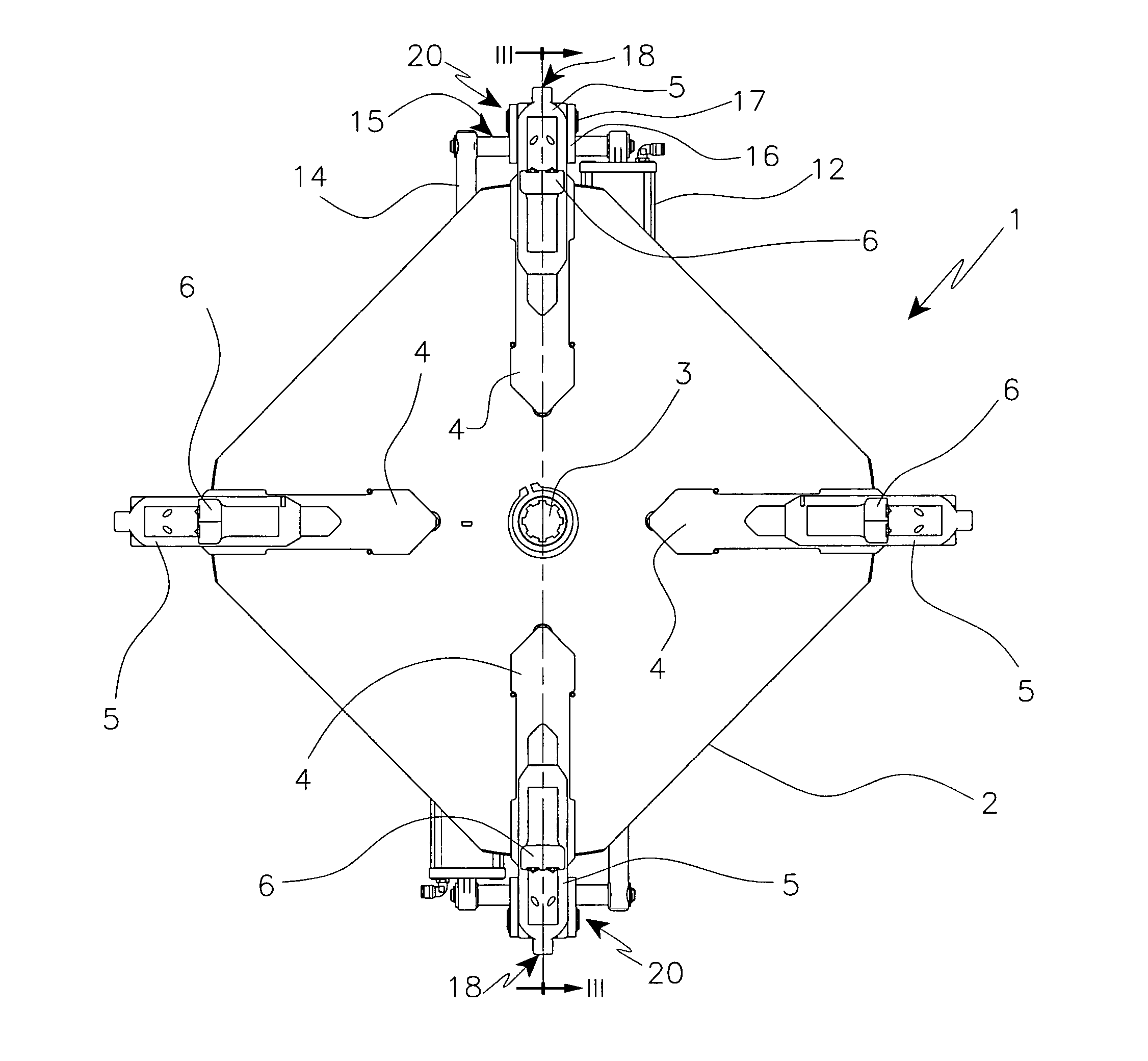
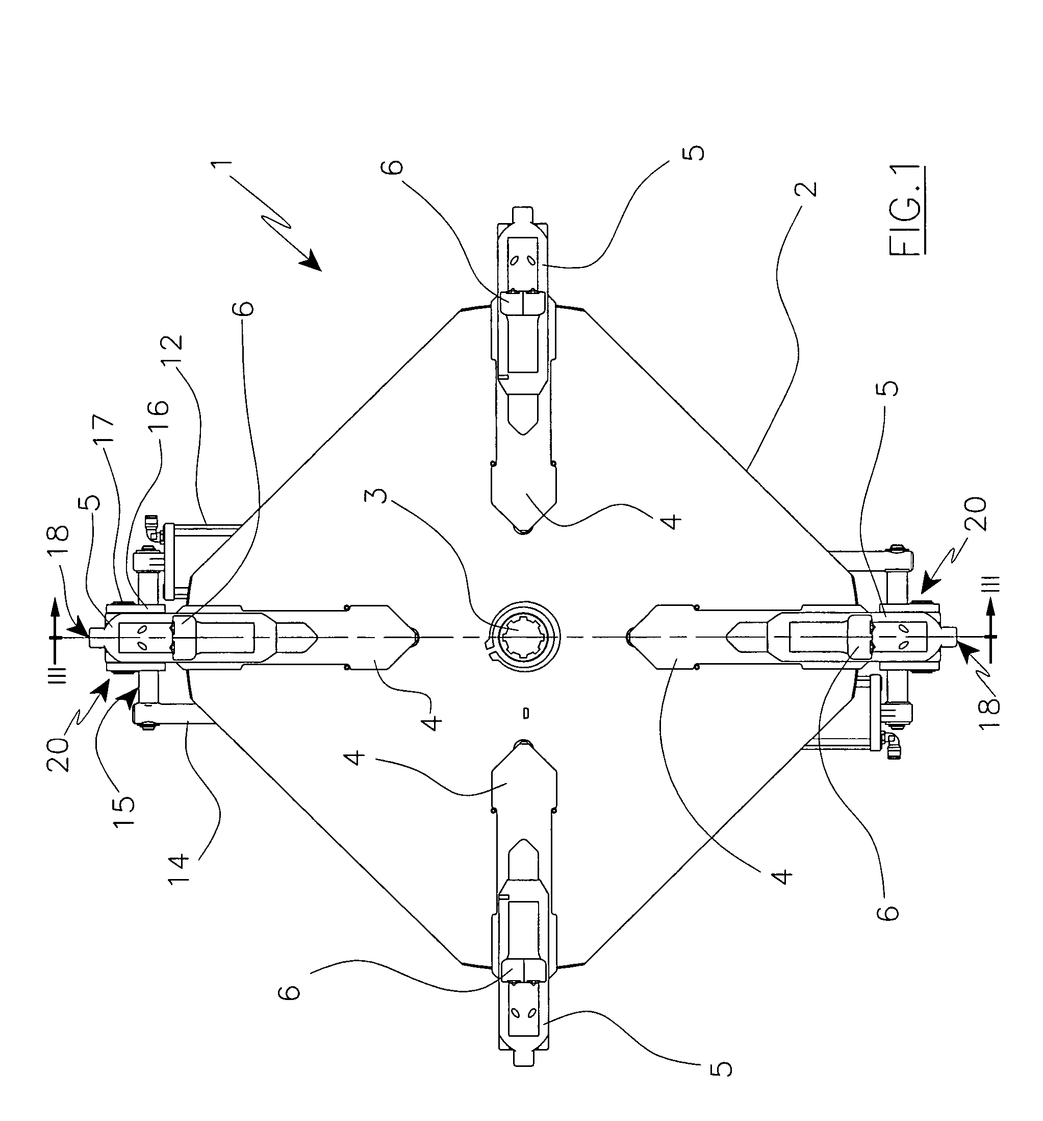
[0020]Said figures show a self-centering unit 1 comprising a horizontal plate 2 to be associated with a vertical shaft 3 branching from the base of a usual tire removal machine, not shown.

[0021]The purpose of the shaft 3 is to rotate the self-centering unit 1 during the demounting or mounting of the tire from or on the wheel rim by the usual means with which the tire removal machine is provided.

[0022]The plate 2 presents four angularly equidistant identical radial slots 4. In each slot 4 there is slidingly mounted a slide 5 (FIG. 1) provided on its upper side with a double acting clamping jaw 6, i.e. able to lock a wheel rim 7, shown by dashed and dotted lines in FIG. 3, from the inside or from the outside.

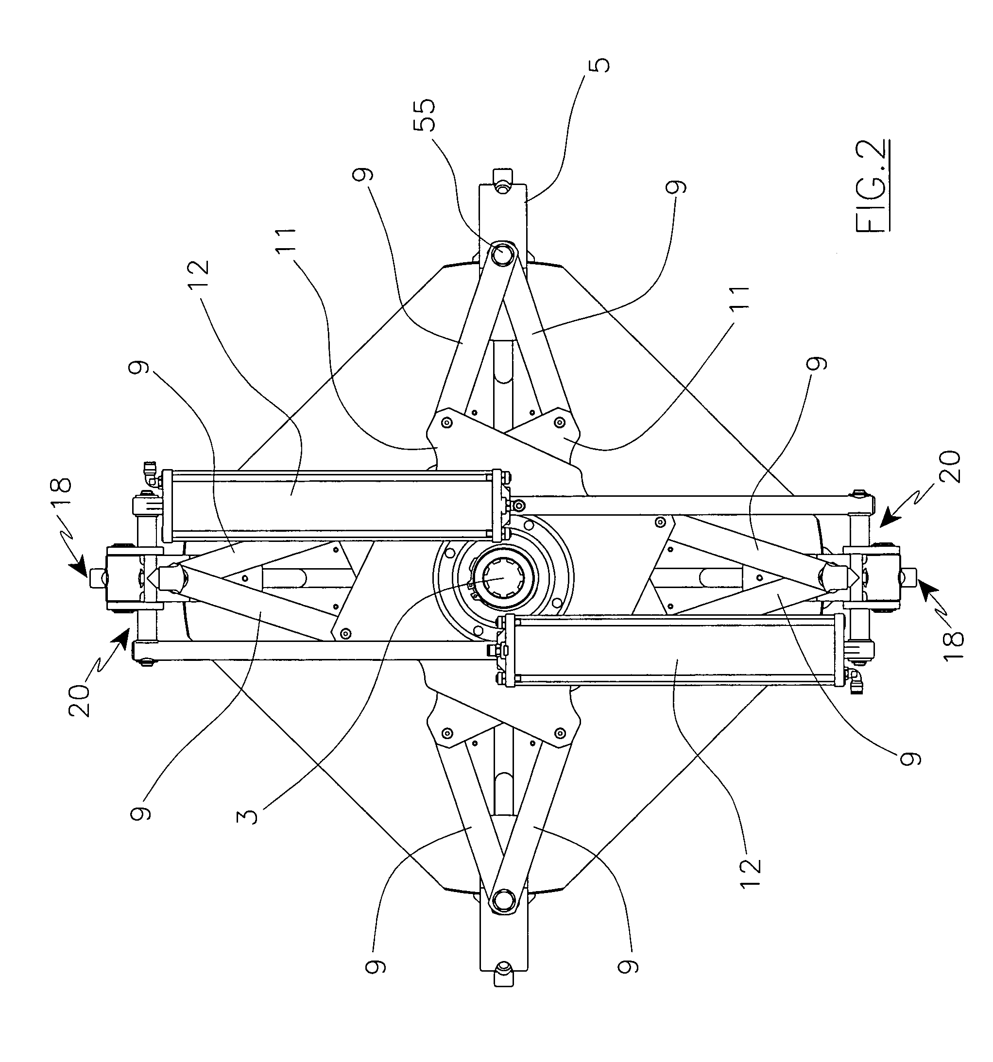
[0023]With reference to FIGS. 2, 3 and 4, each slide 5 lowerly presents a threaded pin 55 (FIG. 4), the axis of which intersects the longitudinal axis of the corresponding radial slot 4, and on which there is mounted a bushing 8 on which a pair of identical overlying connecting ro...


PUM


Abstract

Self-centering unit for tire removal machines, comprising a plate provided with a series of angularly equidistant radial slots, in each of which a clamping jaw is received and slides to grip the edge of a wheel rim, said clamping jaws being linked together in such a manner as to be always equidistant from the axis of said plate, at least one clamping jaw being associated with actuator means causing it to translate in a radial direction by means of a positioner device arranged to vary the working position of said clamping jaws relative to the actuator means, without modifying their travel stroke.

Description

FIELD OF THE INVENTION[0001]The present patent relates to a self-centering unit to be associated with tire removal machines, to maintain wheel rims locked in a horizontal position while demounting and / or mounting the corresponding tires.PRIOR ART[0002]The automobile industry currently markets vehicles provided with wheel rims of a diameter which exceeds the range within which traditional self-centering units operate.[0003]To be able to also operate on large-dimension wheel rims, a self-centering unit is known comprising a horizontal plate mounted on an underlying vertical shaft of the tire removal machine. Said plate presents a circumferential series of angularly equidistant radial slots, with each of which there is associated a slide carrying a head or clamping jaw for gripping the edge of the wheel rim from the inside or outside.[0004]The head is associated with the slide in such a manner as to be able to translate in the direction of the travel axis of the slide in order to occup...

Claims


Application Information

Patent Timeline
Patent Type & Authority Patents(United States)
IPC IPC(8): B60C25/00B60B30/06B60C25/132
CPCB60C25/0545B60C25/132B60C25/0539
Inventor CORGHI, REMOSANTORO, ENRICO
Owner NEXION SPA
Why Eureka
Try Eureka