Method and apparatus for aligning rotor in stator of a rod driven well pump

a technology of rod driven well pump and stator, which is applied in the direction of piston pump, positive displacement liquid engine, borehole/well accessories, etc., can solve the problems of affecting pumping capacity and creating obstruction

Inactive Publication Date: 2007-04-10
BAKER HUGHES INC
View PDF10 Cites 70 Cited by
  • Summary
  • Abstract
  • Description
  • Claims
  • Application Information

AI Technical Summary

Problems solved by technology

If the lower end of the rotor is spaced above a lower end of the stator during operation, then a lower portion of the stator will not be in engagement with the rotor and the pumping capacity will suffer.
While this method works well enough, tag bar creates an obstruction at the bottom of the pump.

Method used


Image

  • Method and apparatus for aligning rotor in stator of a rod driven well pump
  • Method and apparatus for aligning rotor in stator of a rod driven well pump
  • Method and apparatus for aligning rotor in stator of a rod driven well pump

Examples


Embodiment Construction

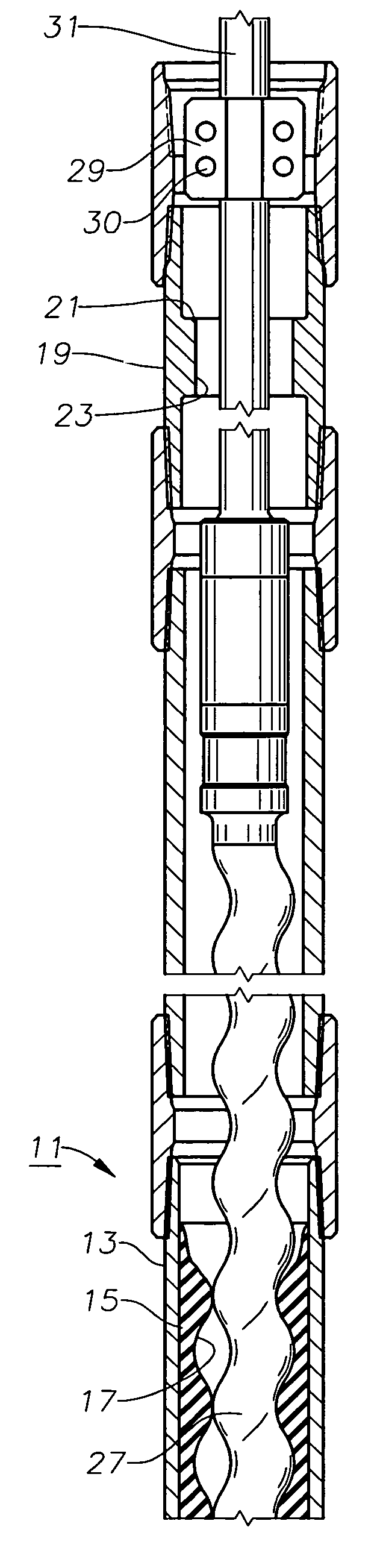
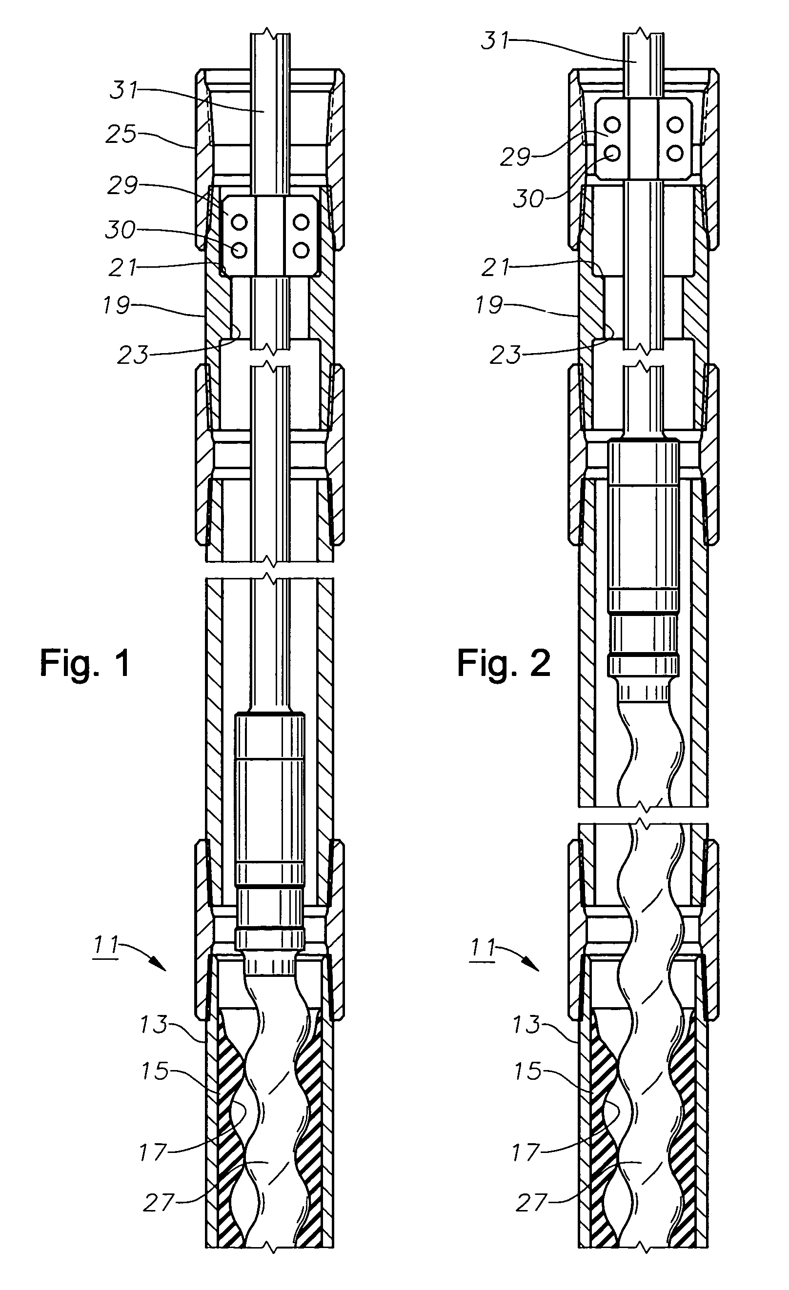
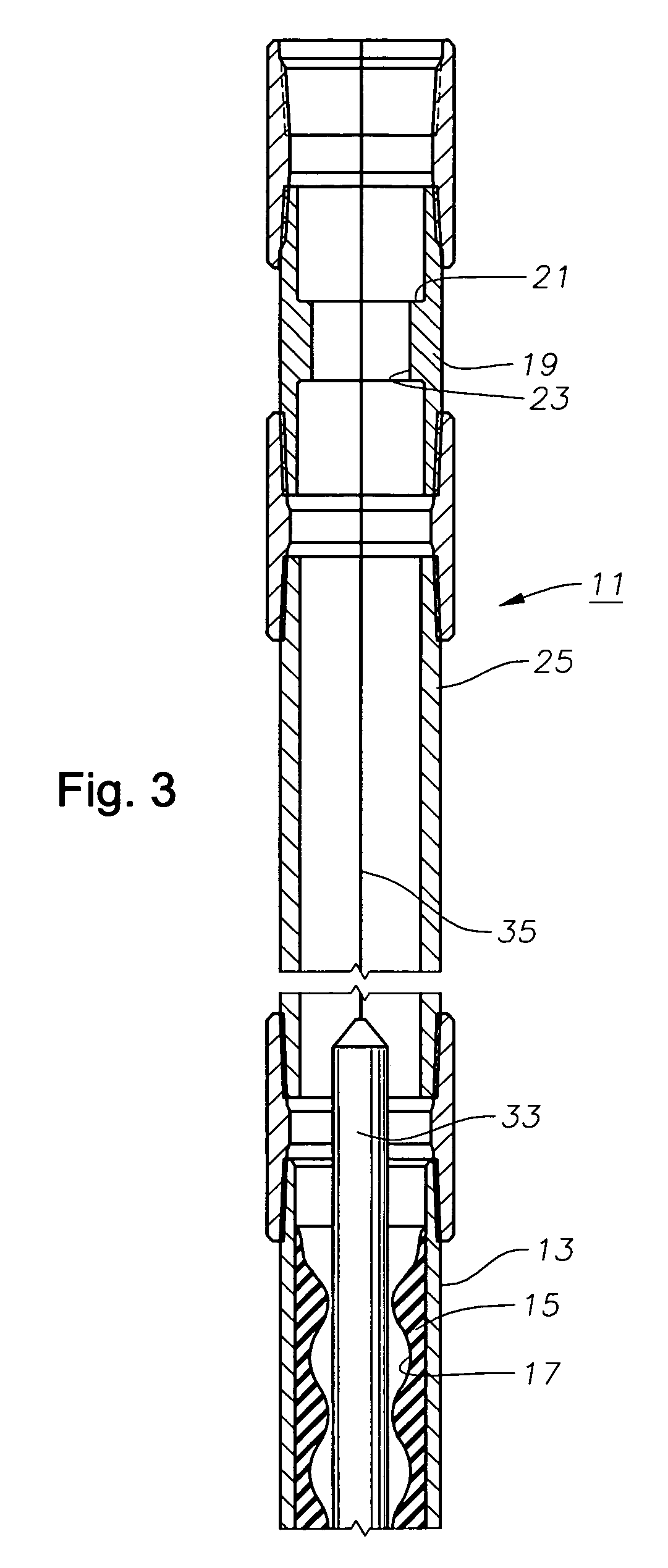
[0014]Referring to FIG. 1, progressing cavity pump 11 has a stator 15 that is fixed within a housing 13. Housing 13, which may be considered a part of stator 15, is normally of metal while stator 15 is normally of a deformable elastomeric material. A helical passage 17 configured in a double helix extends through stator 15 in a manner that is conventional to progressing cavity pumps. Pump 11 is suspended on the end of a string of production tubing 25.

[0015]A sub 19 is mounted within tubing string 25 above stator housing 13. Sub 19 has a passage 23 containing a tag shoulder 21. In this embodiment, tag shoulder 21 is annular and faces upward. The inner diameter of passage 23 at tag shoulder 21 is equal to or slightly greater than the minimum inner diameter of passage 17 of stator 15. Tag shoulder 21 is shown as a flat surface that is perpendicular to the longitudinal axis of stator 15, but it could be conical, if desired. Passage 23 optionally may have an outward flared portion below ...


PUM


Abstract

A progressing cavity rod-driven well pump utilizes a tag shoulder above a helical passage of the stator. The pump stator is located at the lower end of a string of tubing. The tag shoulder is more restrictive than a passage through the tubing. A pump rotor is secured to a string of rods and has a stop located above the rotor. The rotor is lowered on the rods until the stop lands on the tag shoulder. Then the operator lifts the rods and the rotor to accommodate for expected stretch during operation. By removing the rods and rotor, monitoring tools can be lowered through the tag shoulder and stator.

Description

FIELD OF THE INVENTION[0001]This invention relates in general to progressing cavity rod driven well pumps that are driven by a motor at the surface, and particularly to a method and apparatus for axially spacing the rotor within the stator.BACKGROUND OF THE INVENTION[0002]A progressing cavity pump has a stator and a rotor. The stator typically comprises an elastomeric liner within a housing. The stator is open at both ends and has a double helical passage extending through it. The rotor is normally of metal and has a single helical exterior formed on it. Rotating the rotor causes fluid to pump through the stator. Progressing cavity pumps are used for a variety of purposes.[0003]As a well pump, progressing cavity pumps may be driven by a downhole electrical motor or by a string of rods extending to a motor located at the surface. With a rod driven pump, normally the stator is suspended on a string of tubing, and the drive rods are located within the tubing. When installing a rod driv...

Claims


Application Information

Patent Timeline
Patent Type & Authority Patents(United States)
IPC IPC(8): E21B43/00E21B43/12F04C13/00
CPCE21B43/126F04C13/008
Inventor KANADY, EDWARD C.PROCTOR, BRUCE E.
Owner BAKER HUGHES INC
Why Eureka
Try Eureka