Disk brake devices

a technology of brake device and disc, which is applied in the direction of noise/vibration control, slack adjuster, brake elements, etc., can solve the problems of large friction force generated between the pad and the mount, and the pad cannot move smoothly in the axial direction, so as to facilitate the pivoting movement, reduce rigidity, and facilitate the effect of movemen

Active Publication Date: 2007-04-10
ADVICS CO LTD
View PDF13 Cites 23 Cited by
  • Summary
  • Abstract
  • Description
  • Claims
  • Application Information

AI Technical Summary

Benefits of technology

[0007]It is accordingly an object of the present invention to teach improved floating-type disk brakes, in which a disk brake pad is facilitated to move along an axial direction of a brake disk.

Problems solved by technology

However, because the pad is tightly pressed against the mount by the biasing force of the resilient arms and by the moment produced by the brake disk, a very large friction force is generated between the pad and the mount when the pad is moved in the axial direction of the brake disk.
In such a case, the pad cannot move smoothly in the axial direction.

Method used


Image

  • Disk brake devices
  • Disk brake devices
  • Disk brake devices

Examples


first representative embodiment

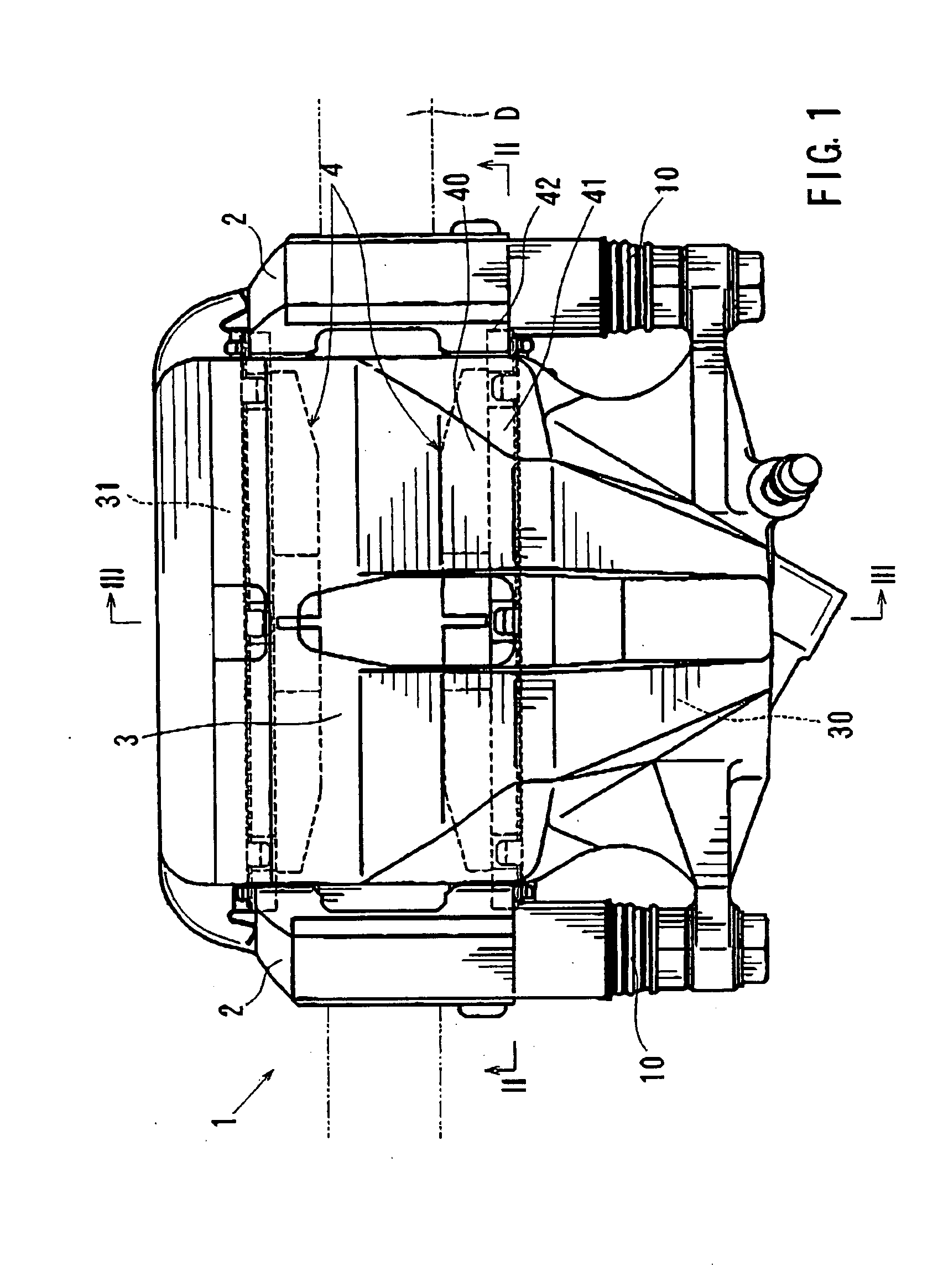
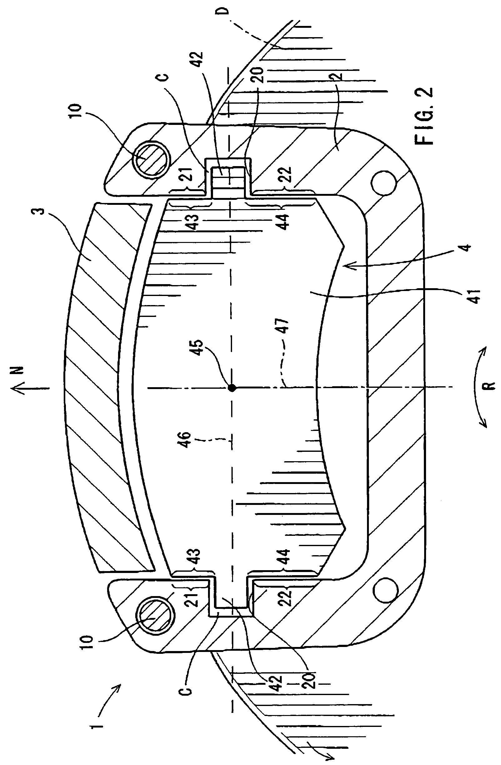
[0057]A first representative embodiment of the present invention will now be described with reference to FIGS. 1 to 3. As shown in FIG. 1, a brake device 1 according to the first representative embodiment generally includes a pair of pads 4, a mount 2, and a caliper 3. The mount 2 is adapted to be attached to a vehicle, such as an automobile (not shown). The pads 4 are supported on the mount 2 and positioned opposing an inner side surface and an outer side surface of the brake disk D (hereinafter simply called “inner side” and “outer side”) The terms “inner side” and “outer side” are determined relative to the vehicle (i.e., the side nearest to the exterior of the vehicle is the “outer sided”).

[0058]The caliper 3 is mounted on the mount 2 via slide pins 10 that are slidably movable relative to the mount 2. Consequently, the caliper 3 is movable relative to the mount 2 in an axial direction of the brake disk D via the slide pins 10. As a result, the brake disk D is typically centered...

second representative embodiment

[0074]A second representative embodiment will now be described with reference to FIGS. 4 through 8. The second representative embodiment is a modification of the first representative embodiment. Therefore, in FIGS. 4 to 8, like members are given the same reference numerals as FIGS. 1 to 3. The description of these members will not be repeated.

[0075]In this second representative embodiment, as shown in FIG. 4, support members 5 are fitted into the clearances C that are formed between the guide portions 42 of the pads 4 and the support portions 20 of the mount 2. The support member 5 serves to prevent the guide portions 42 and the support portions 20 from directly contacting one another. In addition, the support member 5 aids in preventing the wear and grinding together of the guide portions 42 and the support portions 20.

[0076]Referring to FIG. 5, each of the support members 5 is made of a spring plate. The support members 5 have an integral structure with a pair of pressure receivin...

third representative embodiment

[0092]A third representative embodiment will now be described with reference to FIG. 9. The third representative embodiment is a modification of the second representative embodiment. Therefore, in FIG. 9, like members are given the same reference numerals as in FIGS. 4 to 8. The description of these members will not be repeated.

[0093]The third representative embodiment is different from the second representative embodiment mainly in the use of separate resilient members 90 and 91, configured for example as coil springs, in place of support member 5. The resilient members 90 and 91 are disposed within the clearance C formed between the guide portion 42 and the corresponding support portion 20.

[0094]The resilient member 90 is interposed between the radially outward side surface 20a of the support portion 20 and the radially outward guide surface 42a of the guide portion 42. The resilient member 90 is deformed or compressed in order to fit within the clearance C. Therefore, the resilie...


PUM


Abstract

A disk brake device has a rotary brake disk, at least one pad, and a mount. The pad has a guide portion disposed on one end of the pad in the rotational direction of the brake disk. The mount has a support portion that slidably supports the guide portion, so that the pad can move in the axial direction of the brake. A radially outer pressure receiving surface and a radially inner pressure receiving surface are formed on an end of the pad in the rotational direction of the brake disk and serve to receive a reaction force from the mount in order to prevent the pad from moving in the rotational direction of the brake disk. A support member serves to bias the pad in an axial and rotational direction so as to reduce the production of audible sounds.

Description

[0001]This application claims priority to Japanese patent application serial numbers 2003-353693, 359729 and 378316, the contents of which are incorporated herein by reference.BACKGROUND OF THE INVENTION[0002]1. Field of the Invention[0003]The present invention relates to disk brake devices known as floating-type disk brake devices. In particular, the present invention relates to floating-type disk brake devices in which a guide portion, disposed on at least one end of a disk pad in a rotational direction of a disk pad, is supported by a support portion provided on a mount such that the guide portion is movable in an axial direction of the disk but is prevented from being removed from the support portion along the radial direction of the disk pad.[0004]2. Description of the Related Art[0005]Floating-type disk brakes having various constructions are known. For example, Japanese Laid-Open Patent Publication No. 2000-27905 (U.S. Pat. No. 3,303,780) teaches a disk brake in which guide p...

Claims


Application Information

Patent Timeline
Patent Type & Authority Patents(United States)
IPC IPC(8): F16D65/40F16D55/00F16D55/227F16D65/00F16D65/097
CPCF16D55/227F16D65/0006F16D65/0972
Inventor NAKAJIMA, MASAHIKOMATSUZAKI, YOSHIKI
Owner ADVICS CO LTD
Why Eureka
Try Eureka