Method and apparatus for routing pages to printers in a multi-print engine as a function of print job parameters

a multi-print engine and print job technology, applied in the field of electrotrophotographic printers, can solve the problems of inability to always direct translation between, inability to determine the low toner level of the cartridge, and limited printing throughput of complex printing jobs involving multiple copies of multiple-page documents having both monochrome and/or color printing requirements

Inactive Publication Date: 2007-04-17
ELECTRONICS FOR IMAGING INC
View PDF59 Cites 16 Cited by
  • Summary
  • Abstract
  • Description
  • Claims
  • Application Information

AI Technical Summary

Problems solved by technology

However, in a multipass color process, multiple images must be superimposed on one another on the sheet of paper in a direct transfer system, thus requiring multiple passes of the paper or image carrier through the print engine.
From the foregoing it is clear that printing throughput for complex printing jobs involving multiple copies of multiple-page documents having both monochrome and / or color printing requirements is limited by the speed of the slowest print engine used to print the documents.
This system poses a significant problem, however, of how to most efficiently organize and route the parts of a complex print job to the plurality of print engines in a multiple print engine printing system.
When dealing with multiple print engines, there can be a problem that exists with respect to insuring that there is adequate “color balance”.
They do not always have a direct translation between them, however.
As such, the determination of a low toner level in a cartridge is extremely inaccurate.

Method used


Image

  • Method and apparatus for routing pages to printers in a multi-print engine as a function of print job parameters
  • Method and apparatus for routing pages to printers in a multi-print engine as a function of print job parameters
  • Method and apparatus for routing pages to printers in a multi-print engine as a function of print job parameters

Examples


Embodiment Construction

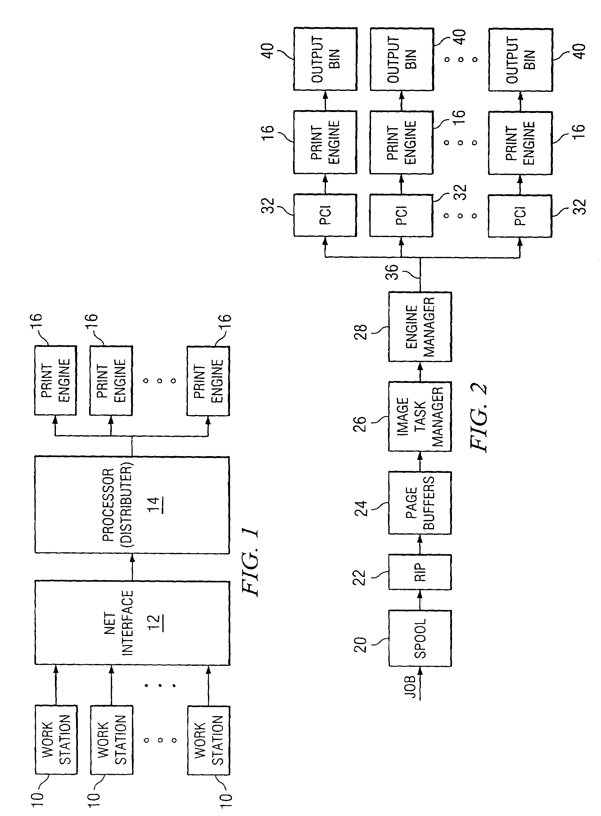
[0049]Referring now to FIG. 1, there is illustrated a block diagram of the overall operation of the virtual printing system. A plurality of workstations 10 are provided, which workstations 10 comprise general personal computers or other terminals that allow a user to create print jobs. Each of the workstations is networked through a network interface 12, which is a conventional type of general network interface such as an Ethernet® network interface. This allows each workstation 10 to send its print job to a central processor 14, which processor is operable to process the print jobs in accordance with the system of the present invention and distribute these print jobs to multiple print engines 16. As will be described herein below, the processor 14 is operable to disassemble the print job, parse the print job into different pages and distribute the parsed pages in a predetermined manner in accordance with the present invention. It should be understood that a print job, although init...


PUM


Abstract

A method and apparatus for routing page data of a print job to the printers in a multi-print engine based on print job parameters associated with the page data of the print job is disclosed. One or more virtual printers are configured, each with a plurality of individual print engines, each having associated printing characteristics. Page data of the print job, downloaded form a print file and having the print job parameters associated therewith, is rasterized and stored as bit-mapped images in print buffers associated with the multi-engined printing system. The bit-mapped images are distributed to select ones of the print engines based upon matching the print job parameters of each bit-mapped images with the printing characteristics of the print engine to be selected.

Description

CROSS REFERENCE TO RELATED APPLICATIONS[0001]This application is a Continuation of U.S. patent application Ser. No. 09 / 227,657, filed Jan. 8, 1999 now U.S. Pat. No. 6,606,165, which is a Continuation of U.S. patent application Ser. No. 08 / 698,999, filed Aug. 16, 1996 now U.S. Pat. No. 5,859,711, which is a Continuation-In-Part of U.S. patent application Ser. No. 08 / 511,641, filed Aug. 7, 1995 now U.S. Pat. No. 6,657,741.TECHNICAL FIELD OF THE INVENTION[0002]The present invention pertains in general to electrophotographic printers and, more particularly, to a plurality of print engines configured to process print jobs in a parallel manner.BACKGROUND OF THE INVENTION[0003]Electrophotographic print engines have been utilized with both printers and copiers. In a printer, the print engine is typically interfaced with a computer to select and organize fonts or bit map the images. In a copier application, the print engine is interfaced with an input device that scans the image onto the pho...

Claims


Application Information

Patent Timeline
Patent Type & Authority Patents(United States)
IPC IPC(8): G06F15/00G06K15/00B41J29/38B41F1/00G06F3/12G06K1/00G06K15/02G06K15/14H04N1/29H04N1/50H04N1/52H04N1/56H04N1/60
CPCB41J29/393G06F3/1211G06F3/1215G06F3/1217G06F3/124G06F3/1241G06F3/1281G06F3/1282G06K15/02G06K15/1806G06K15/1857G06K15/1856G03G15/5087G03G15/5062Y02B60/1271G03G2215/00021G03G2215/0005G03G2215/00109G06F3/1285G06F2206/1514Y02D10/00G06F3/12
Inventor BARRY, MICHAEL W.BARTHOLMAE, JACK N.ROWE, FRANCIS A.TOMPKINS, E. NEALZUBER, PETER A.
Owner ELECTRONICS FOR IMAGING INC
Why Eureka
Try Eureka