Crown molding clamp

a clamping and clamping technology, applied in the field of clamps, can solve the problem that the clamping is difficult for one worker to handle without assistan

Inactive Publication Date: 2007-05-01
BLAU KARL T
View PDF12 Cites 10 Cited by
  • Summary
  • Abstract
  • Description
  • Claims
  • Application Information

AI Technical Summary

Benefits of technology

[0005]The present invention is directed to a novel crown molding clamp which enables one worker, without assistance from another, to more readily affix long pieces of crown molding along the walls of a room at the ceiling. The present clamp is adjustable to fit crown molding of different sizes and configurations.

Problems solved by technology

Because of its length the crown molding is difficult for one worker to handle without assistance as the nailing proceeds from one wall stud to the next across the wall.

Method used


Image

  • Crown molding clamp
  • Crown molding clamp
  • Crown molding clamp

Examples


Embodiment Construction

[0021]Before explaining the present invention in detail it is to be understood that the invention is not limited in its application to the particular arrangements shown and described since the invention is capable of other embodiments. Also, the terminology used herein is for the purpose of description and not of limitation.

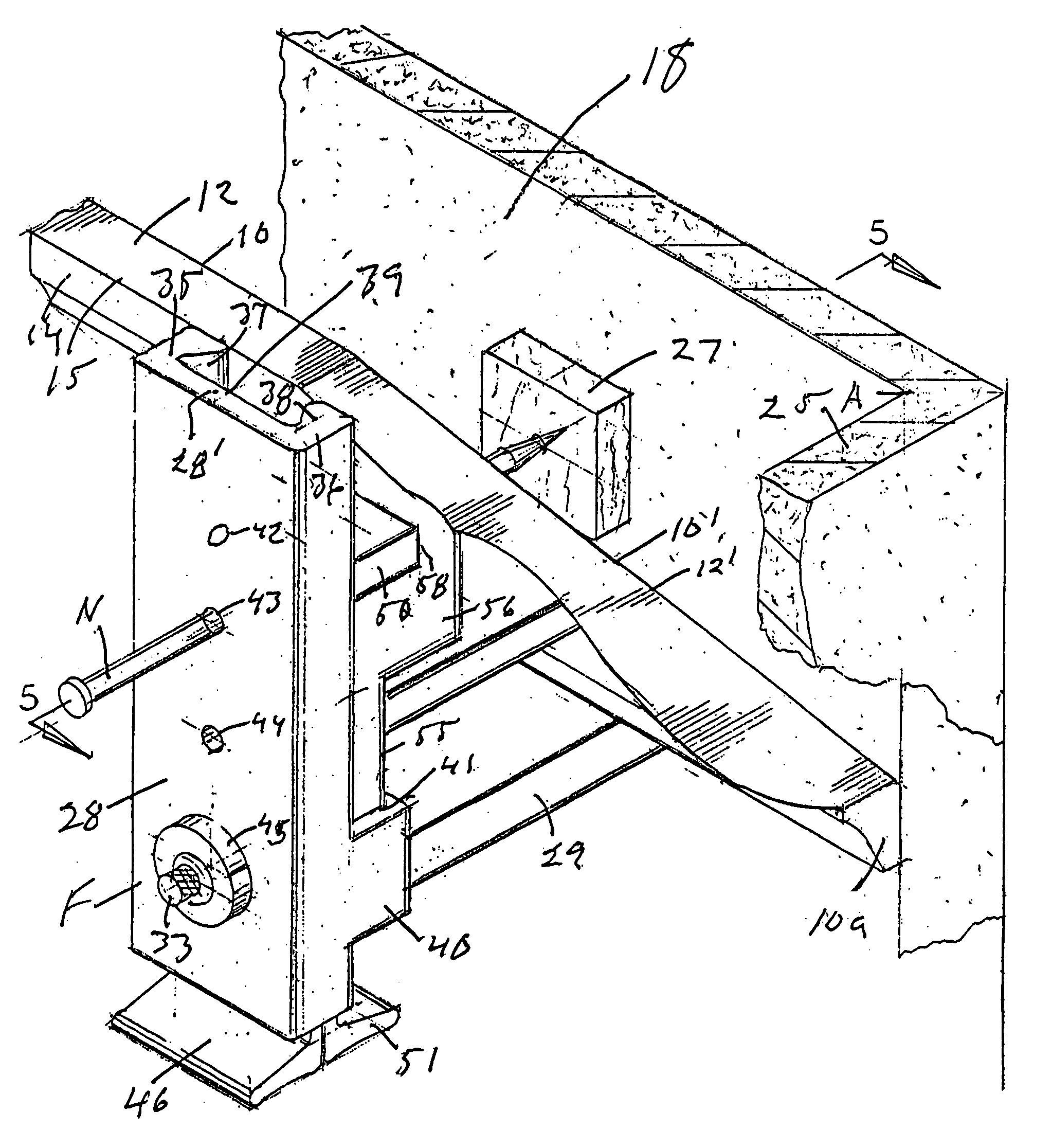
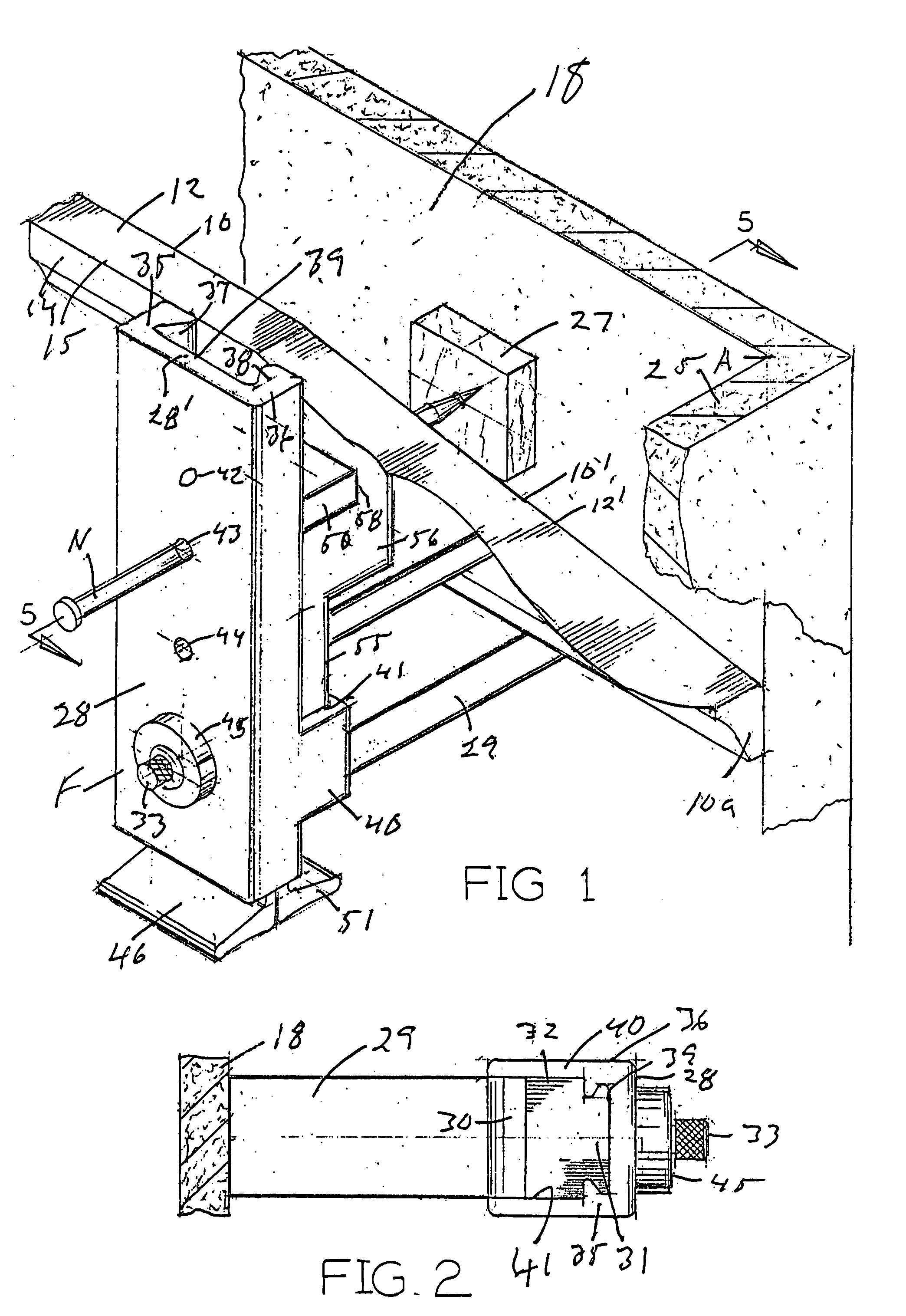
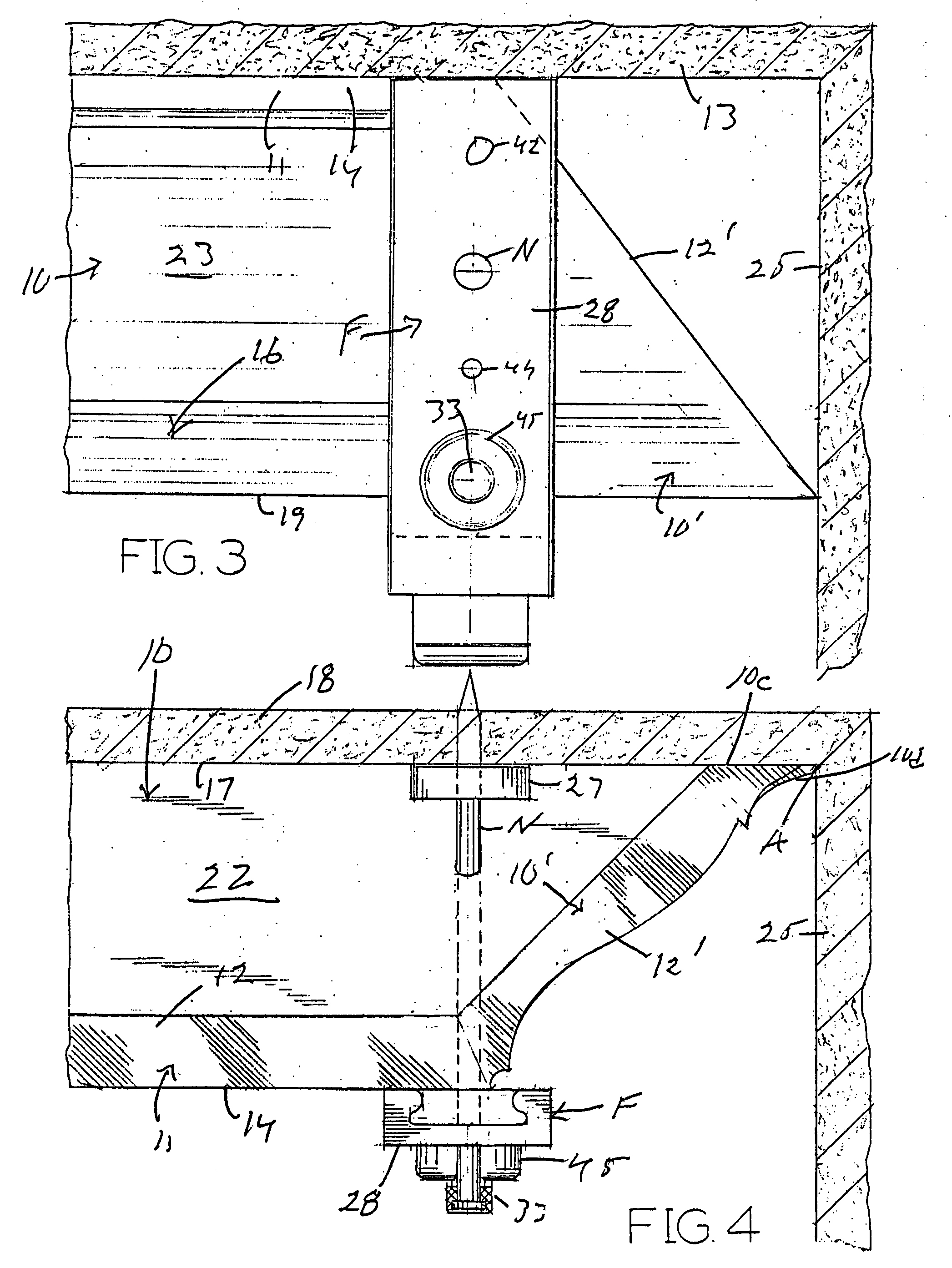
[0022]As shown in FIGS. 1–4, the first embodiment of the present clamp is adjusted for use in installing relatively large sized crown molding 10 which has a forwardly projecting, horizontal top lip 11 at the front (FIG. 5) with a flat horizontal top face 12 for engaging the ceiling 13 of the room except in the vicinity of a corner of the room at each end of the crown molding, such as the corner A in FIG. 1 at the right end of the crown molding where adjoining side walls 18 and 25 of the room meet. The top front lip 11 has a flat vertical front face 14 extending down from its top face 12 at a right-angled top front corner 15 (FIG. 1). The crown molding has an oppo...


PUM


Abstract

A clamp for use in installing crown molding which has a top front lip, a bottom rear lip and a bridging segment extending diagonally between them, comprising a clamp part for engaging the ceiling of a room and for engaging the top front lip of the crown molding from in front, and another clamp part for engaging the bottom rear lip of the crown molding from below and engaging the room wall behind the crown molding.

Description

BACKGROUND OF THE INVENTION[0001]1. Field of the Invention[0002]This invention relates to a clamp to facilitate installing crown molding along the periphery of the ceiling of a room.[0003]2. Prior Art[0004]When crown molding is installed on the walls of a room at the ceiling, usually each piece of the molding is long and therefore somewhat flexible, preferably long enough to extend completely across the wall to which it is to be nailed, or substantially so. Because of its length the crown molding is difficult for one worker to handle without assistance as the nailing proceeds from one wall stud to the next across the wall.SUMMARY OF THE INVENTION[0005]The present invention is directed to a novel crown molding clamp which enables one worker, without assistance from another, to more readily affix long pieces of crown molding along the walls of a room at the ceiling. The present clamp is adjustable to fit crown molding of different sizes and configurations.[0006]In the presently prefer...

Claims


Application Information

Patent Timeline
Patent Type & Authority Patents(United States)
IPC IPC(8): B25B1/20
CPCE04F21/0069E04F21/185Y10S269/907
Inventor BLAU, KARL T.
Owner BLAU KARL T
Why Eureka
Try Eureka