Idler roll seal

a technology of contact seal and idler, which is applied in the direction of engine seals, roller-ways, shafts and bearings, etc., can solve the problems of corroding chemicals, adversely affecting idler components, and affecting the performance of idlers, so as to fouling, filter out contaminants, and prevent contaminants from infiltrating

Inactive Publication Date: 2012-04-03
NITED STATES STEEL CORP
View PDF8 Cites 22 Cited by
  • Summary
  • Abstract
  • Description
  • Claims
  • Application Information

AI Technical Summary

Benefits of technology

[0007]The present invention is an effective, inexpensive, durable, and easily fabricated and installed idler roll seal for retrofitting existing idler rolls, with each idler roll generally comprising a rotatable cylinder having two opposite ends, each end having an end cap, a fixed axle about which the cylinder rotates, and at least one bearing assembly positioned inside the cylinder for rotatably supporting the cylinder about the fixed axle.
[0008]The invention comprises a disc of rigid polymer or similarly resilient material that is attached preferentially to the outboard end cap of an idler roll to form a protective seal against environmental contamination. A circular aperture through the disc allows the seal when attached to freely rotate about the idler axle with the roll cylinder. One side of the disc—the bottom or roll-facing side—has a raised, flat rim around the periphery of the disc to provide a surface for adhesively attaching the disc to the end cap of the roll. At least one ring of porous material is attached to the bottom of the disc circumferentially about the aperture to filter out contaminants by providing a snug fit when the porous ring is in frictional contact with the end cap of the roll.
[0009]The disc is divided substantially diametrally to create two opposing semicircular half-pieces to facilitate attachment of the seal to the end cap of the idler roll. The half-pieces snap together along cooperating interfaces along opposed diametral faces of the disc. By dividing the disc into two halves, the seal can be easily affixed to the end cap of an idler roll circumferentially about the axle without the need for disassembling or modifying the roll and its supporting brackets. A lip is disposed along the edge of each half and its respective connecting interface, such that the two lips overlap with each other when the two halves are snapped together, thus preventing infiltration of contaminants along the part line where the two halves fit together.

Problems solved by technology

Bulk handling operations that involve raw materials such as coal, coke, and iron ore pellets can subject idlers to excessive moisture, abrasive particulates, contaminants and corrosive chemicals.
Such harsh environmental conditions can adversely affect idler components.
Exposure to contaminants can cause idler roll cylinders to seize up, corrode, and / or prematurely wear out.
Idler failure is most often caused by water, waterborne contaminants, airborne contaminants and combinations thereof seeping through a circumferential gap at the end cap located at each end of a roll cylinder.
Contamination infiltrating the roll via the circumferential gap can result in bearing assembly seizure or roll cylinder corrosion.
In addition, the constant vibration to which idlers are often exposed increases the likelihood of contaminants working their way through the circumferential gap and infiltrating the roll.
Failure of just one bearing assembly or corrosion of just one roll cylinder can necessitate replacement of the entire idler set.
Bearing failure will most often cause the roll to seize and become stationary.
Too many stationary rolls will cause drag on the belt, shortening its life.
The two outer rolls of an idler set, called the wing rolls, are known to fail at a rate significantly greater than the center roll, due to the greater exposure of the wing rolls to the environment, in contrast to the protection afforded to the center roll by the conveyor belt overhead.
Contaminants can only infiltrate the bearing assembly by traversing the tortuous path.
In all of these instances, however, either the seal is part of the inner workings of the idler roll, requiring expensive installation of the seal during roll manufacture, or the seal is externally applied directly to an existing roll, but only after time consuming disassembly of the roll from its bracket.

Method used


Image

  • Idler roll seal
  • Idler roll seal
  • Idler roll seal

Examples


Embodiment Construction

[0028]It should be understood that the application is not limited to the details or methodology set forth in the following description or illustrated in the figures. It should also be understood that the phraseology and terminology employed herein is for the purpose of description only and should not be regarded as limiting.

[0029]While the exemplary embodiments illustrated in the figures and described herein are presently preferred, it should be understood that these embodiments are offered by way of example only. Accordingly, the present application is not limited to a particular embodiment, but extends to various modifications that nevertheless fall within the scope of the appended claims. The order or sequence of any processes or method steps may be varied or re-sequenced according to alternative embodiments.

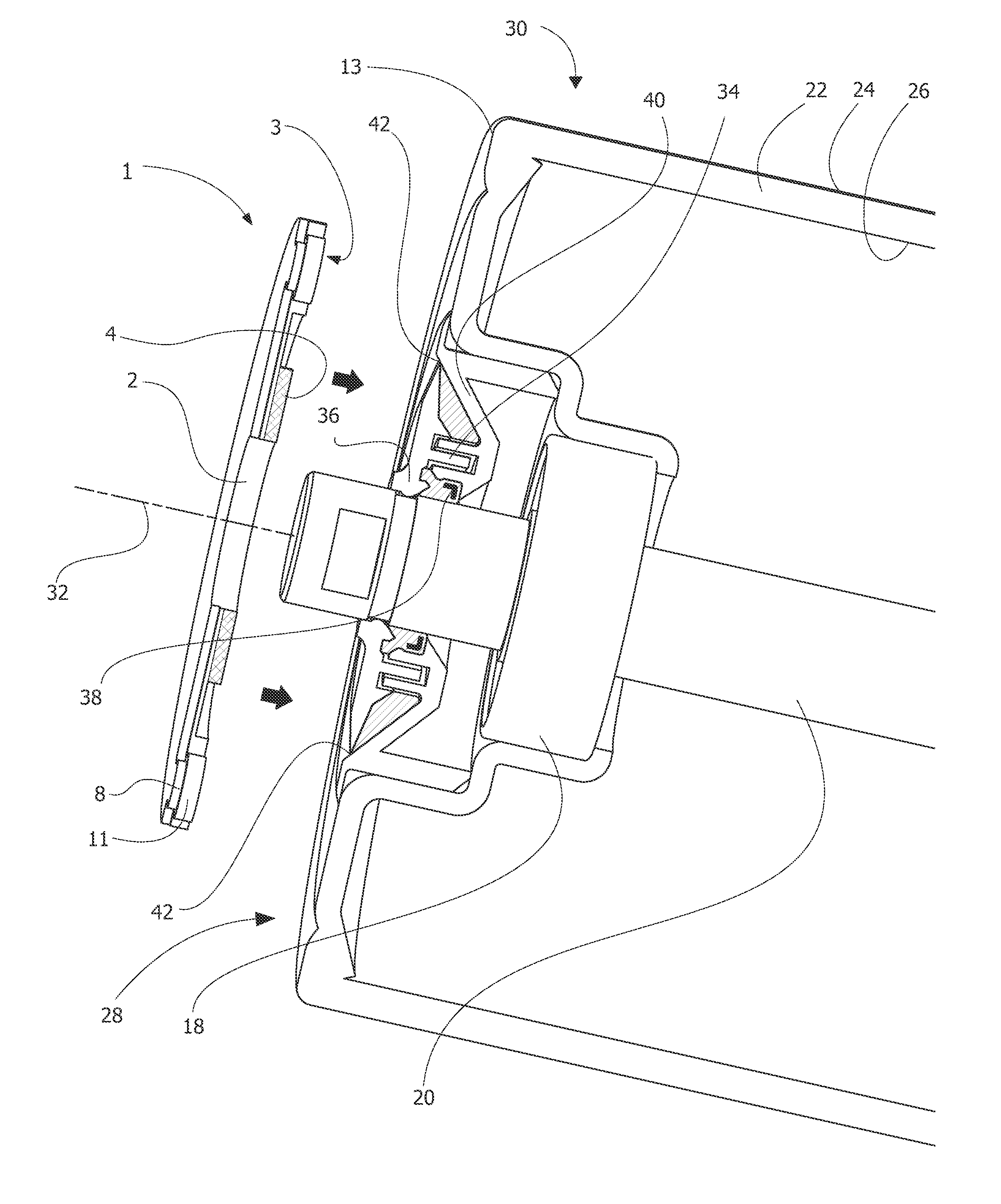
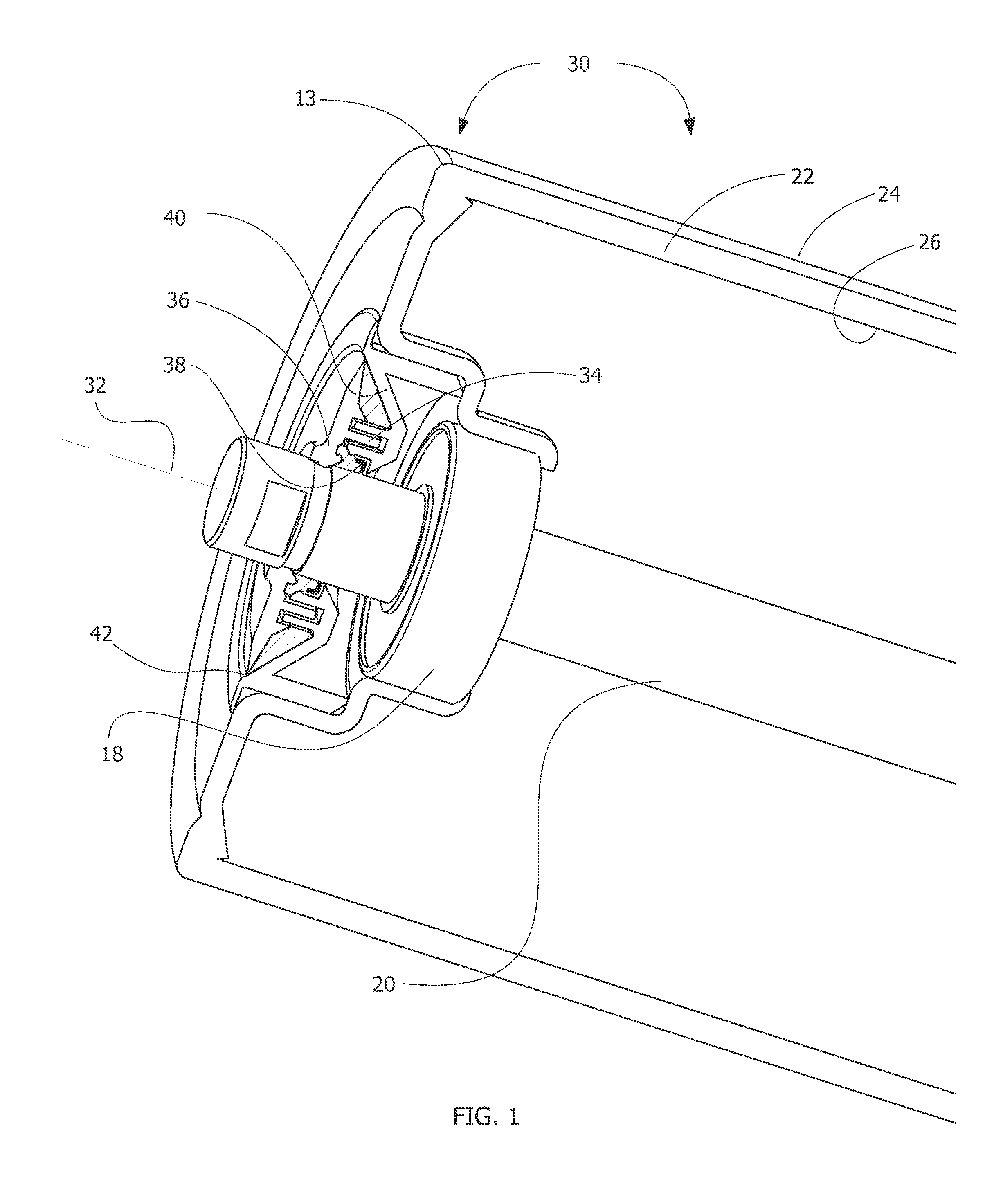
[0030]An axle or shaft 20 is supported at a desired location and orientation on a carrier. The shaft 20 does not rotate but is fixed relative to the carrier. (i.e., stationar...


PUM


Abstract

A contact seal to prevent contamination from fouling a conveyor idler roll, the roll generally comprising a rotatable cylinder, at least one internal bearing assembly, and a fixed axle. A disc of thermoplastic polymer or similarly resilient material is adhesively attached preferentially to an outboard end cap of the idler roll to seal out contamination. A circular aperture through the disc allows the attached seal to rotate about the idler axle. At least one ring of felt or other porous material is adhesively attached to the disc circumferentially to the aperture to filter out contamination when the ring is in frictional contact with the roll end cap. The seal is preferentially divided along the longitudinal axis of the disc to form two interlocking semicircular half-pieces that are snapped together circumferentially about the idler axle so that no disassembly or modification of the idler is required to adhesively attach the seal.

Description

TECHNICAL FIELD OF THE INVENTION[0001]The application generally relates to mechanical seals for bearing assemblies. The application relates more specifically to a contact seal for an idler roller in a conveyor system typically used in industrial manufacturing and mining applications, for preventing contaminants from infiltrating and fouling the idler roll.BACKGROUND OF THE INVENTION[0002]In a belt conveyor line of the type typically used for the bulk handling of raw materials, a continuously moving looped belt and its load are supported by a system of idlers. The idler system comprises idler rolls and supporting brackets, both typically fashioned from steel. Each idler roll generally comprises a roll cylinder having two end caps at each opposite end of the roll cylinder, with the cylinder freely rotating about a fixed axle, the axle being affixed at each end to a supporting bracket, and at least one internal bearing assembly positioned inside the roll cylinder to support the roll cy...

Claims


Application Information

Patent Timeline
Patent Type & Authority Patents(United States)
IPC IPC(8): B65G39/10
CPCB65G39/09
Inventor FOX, PAUL K.
Owner NITED STATES STEEL CORP
Why Eureka
Try Eureka