Flexible optical circuit

a flexible, optical circuit technology, applied in the field of optical circuits, can solve the problems of increasing the complexity of fiber optic infrastructure, increasing the complexity of fiber switching and cross-connecting, and straining the architecture of fiber optic infrastructure, so as to achieve the effect of being easily affixed to the surface during installation

Active Publication Date: 2015-05-12
TYCO ELECTRONICS NETHERLAND BV
View PDF5 Cites 20 Cited by
  • Summary
  • Abstract
  • Description
  • Claims
  • Application Information

AI Technical Summary

Benefits of technology

[0008]The present invention provides a flexible optical circuit having an adhesive bottom that can be readily affixed to a surface during installation. Applicant recognizes that the traditional process of preparing flexible optical circuits can be modified without substantial change to existing production machinery to provide an adhesive portion on the underside of the optical circuit.

Problems solved by technology

The need for increased bandwidth is straining the architecture of fiber optic infrastructure.
With an ever increasing amount of optical transmission, fiber management is more challenging than ever before.
Fiber switching and cross connects add to this complexity as does the density of the individual fiber management systems.
The increasing number of patch cords and fan-out cables required to connect modem infrastructure is problematic not only from a cable management perspective, but also from an operations standpoint (e.g., cooling).
Although use of flexible optical circuits reduces space requirements, Applicant recognizes that space is so limited in many applications that often securing such optical circuits to a cabinet or other framework is problematic.
However, limitations in space may interfere with the use of such devices.

Method used


Image

  • Flexible optical circuit
  • Flexible optical circuit
  • Flexible optical circuit

Examples


Embodiment Construction

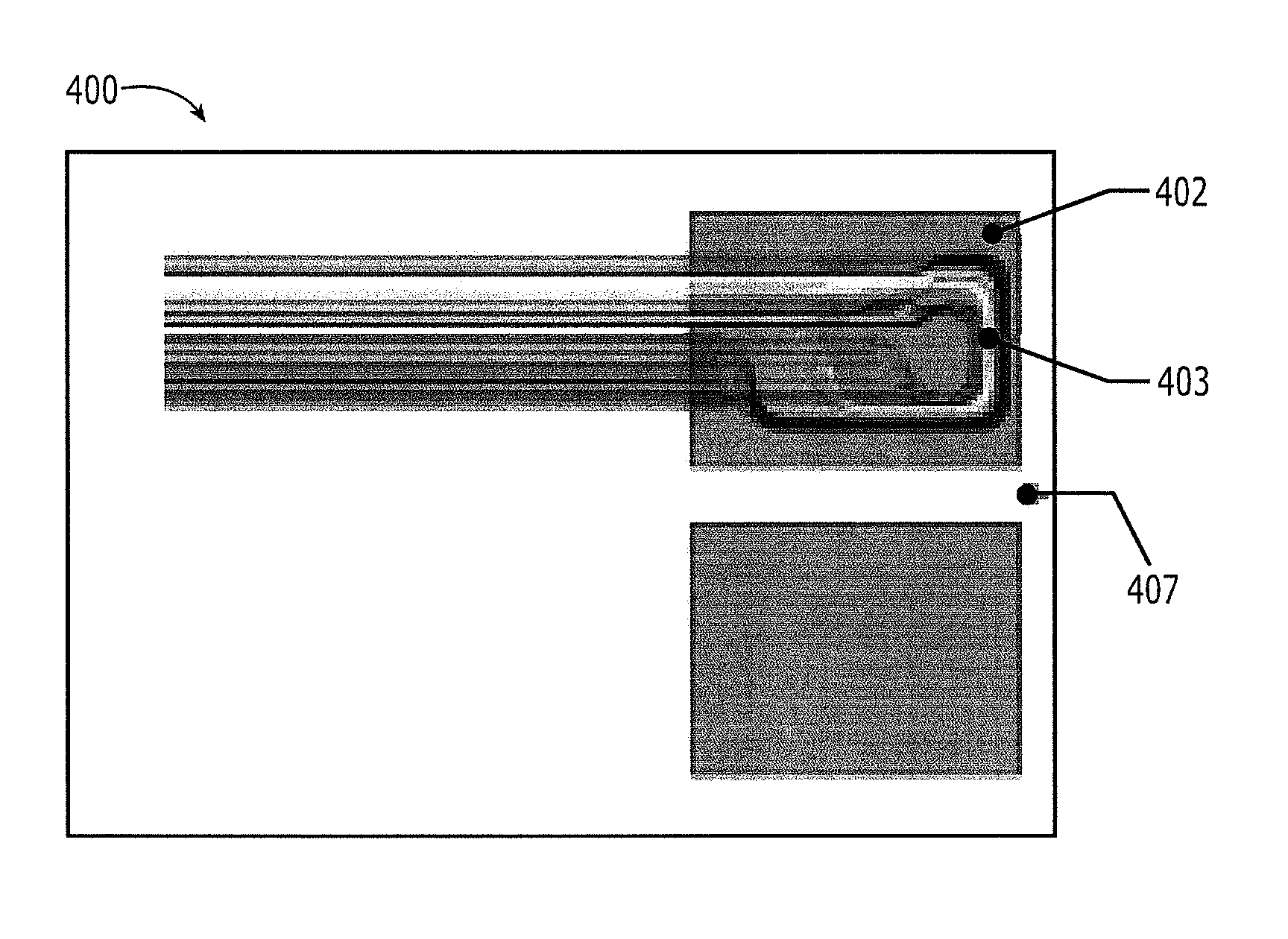
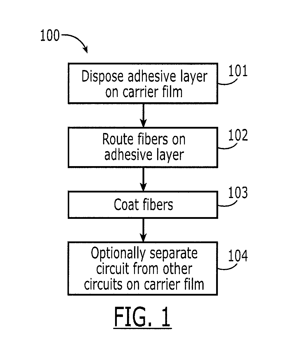
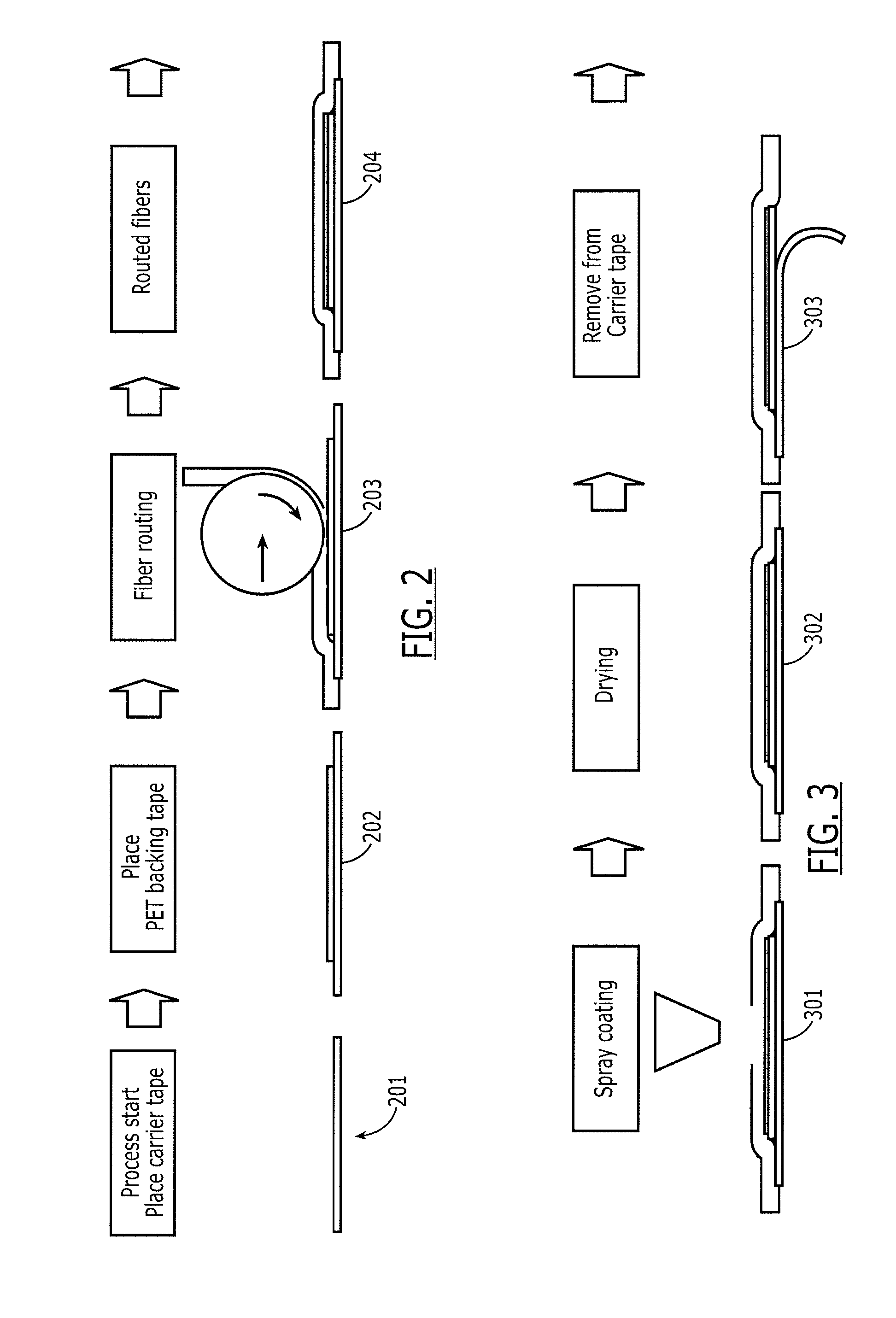
[0017]Referring to FIGS. 1 and 5, one embodiment of the process 100 of manufacturing an optical flexible circuit of the present invention and one embodiment of a flexible optical circuit 500 of the present invention are shown, respectively. First, in step 101, an adhesive layer 502 is disposed on at least a portion of a carrier film 501. The adhesive layer 502 has a downward adhesive face 502a and an upward adhesive face 502b. The downward adhesive face 502a and the carrier film 501 are configured such that the carrier film 501 is removable from the downward face without disruption of the downward adhesive face. In step 102, one or more fibers 503 are routed on the upward adhesive layer 502b. Next, in step 103, a coating 504 is disposed over the fibers to secure them in place, thus defining an optical circuit 500. Optionally, in step 104, the optical circuit 500 is parted from other optical circuits on the carrier film 501.

[0018]The flexible optical circuit 500 prepared from method ...


PUM

PropertyMeasurementUnit
temperatureaaaaaaaaaa
thicknessaaaaaaaaaa
adhesiveaaaaaaaaaa

Abstract

A process of manufacturing an optical flexible circuit comprising: (a) disposing an adhesive layer on at least a portion of a carrier film, said adhesive layer having a downward adhesive face and an upward adhesive face, said downward adhesive face and said carrier film being configured such that said carrier film is removable from said downward adhesive face without disruption of said downward adhesive face; (b) routing one or more fibers on said upward adhesive layer; (c) coating said fibers to define an optical circuit; and (d) optionally parting said carrier film to separate said optical circuit from other optical circuits on said carrier film.

Description

REFERENCE TO RELATED APPLICATION[0001]This application claims priority to U.S. Provisional Application No. 61 / 538,737 filed Sep. 23, 2011, incorporated herein by reference, including its appendix entitled “Fibre Optic Circuits” by Paul Schneider and Sander Dorrestein.FIELD OF INVENTION[0002]The subject matter herein relates generally to optical circuits, and more particularly, to flexible optical circuits.BACKGROUND OF INVENTION[0003]The need for increased bandwidth is straining the architecture of fiber optic infrastructure. With an ever increasing amount of optical transmission, fiber management is more challenging than ever before. Fiber switching and cross connects add to this complexity as does the density of the individual fiber management systems. The increasing number of patch cords and fan-out cables required to connect modem infrastructure is problematic not only from a cable management perspective, but also from an operations standpoint (e.g., cooling).[0004]One approach ...

Claims


Application Information

Patent Timeline
Patent Type & Authority Patents(United States)
IPC IPC(8): G02B6/12A61M16/06G02B6/36
CPCG02B6/3612A61M16/0666A61M16/0683G02B6/4283G02B6/4281
Inventor SCHNEIDER, PAULDORRESTEIN, SANDER
Owner TYCO ELECTRONICS NETHERLAND BV
Why Eureka
Try Eureka