Eureka AIR delivers breakthrough ideas for toughest innovation challenges, trusted by R&D personnel around the world.

High Pressure Connection

a high-pressure connection and connection technology, applied in the direction of hose connection, coupling device connection, borehole/well accessories, etc., can solve the problem of bulky redundancy seal components, and achieve the effect of high-pressure connection, high-pressure connection, and narrow connection

Inactive Publication Date: 2007-05-03
SCHLUMBERGER TECH CORP
View PDF16 Cites 22 Cited by
  • Summary
  • Abstract
  • Description
  • Claims
  • Application Information

AI Technical Summary

Benefits of technology

[0009] It may be desirable for wireline cables or network data transmitting medium in downhole environments to have high pressure connections to their respective downhole tools. It may also be desirable for downhole tools connected in data transmitting systems, hydraulic systems, or pneumatic systems to have high pressure connections with redundant seals. Redundant seals may be desirable in downhole applications utilizing downhole mud hammers because a constant change in pressure may be created by the vibrations of the downhole hammer. A redundant seal may compensate for a primary seal overload during a high pressure peak. Typically, the narrower the connection the easier it is to affix conduits or cables to or within the downhole tool, since the tool typically has limited space to accommodate connections.
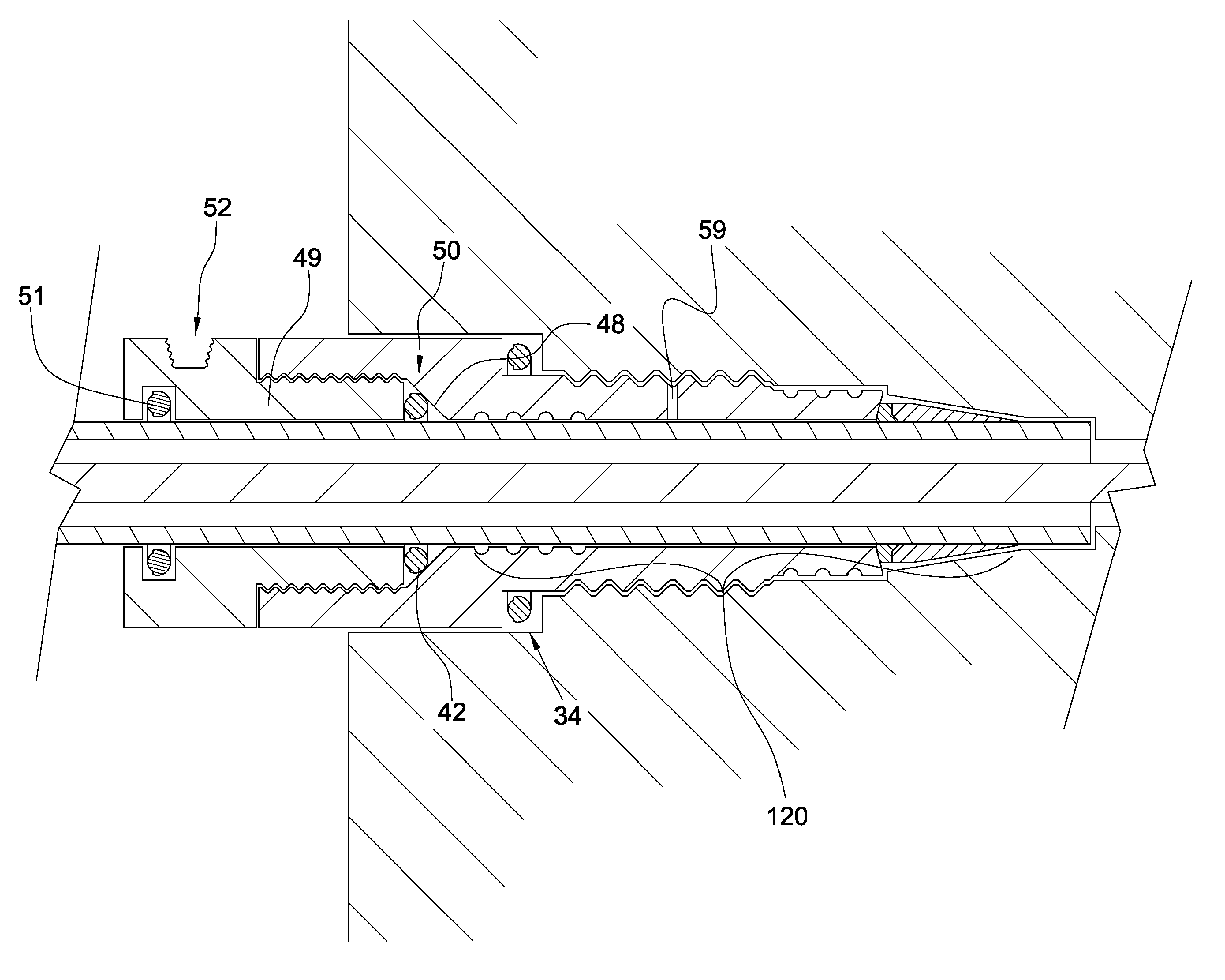
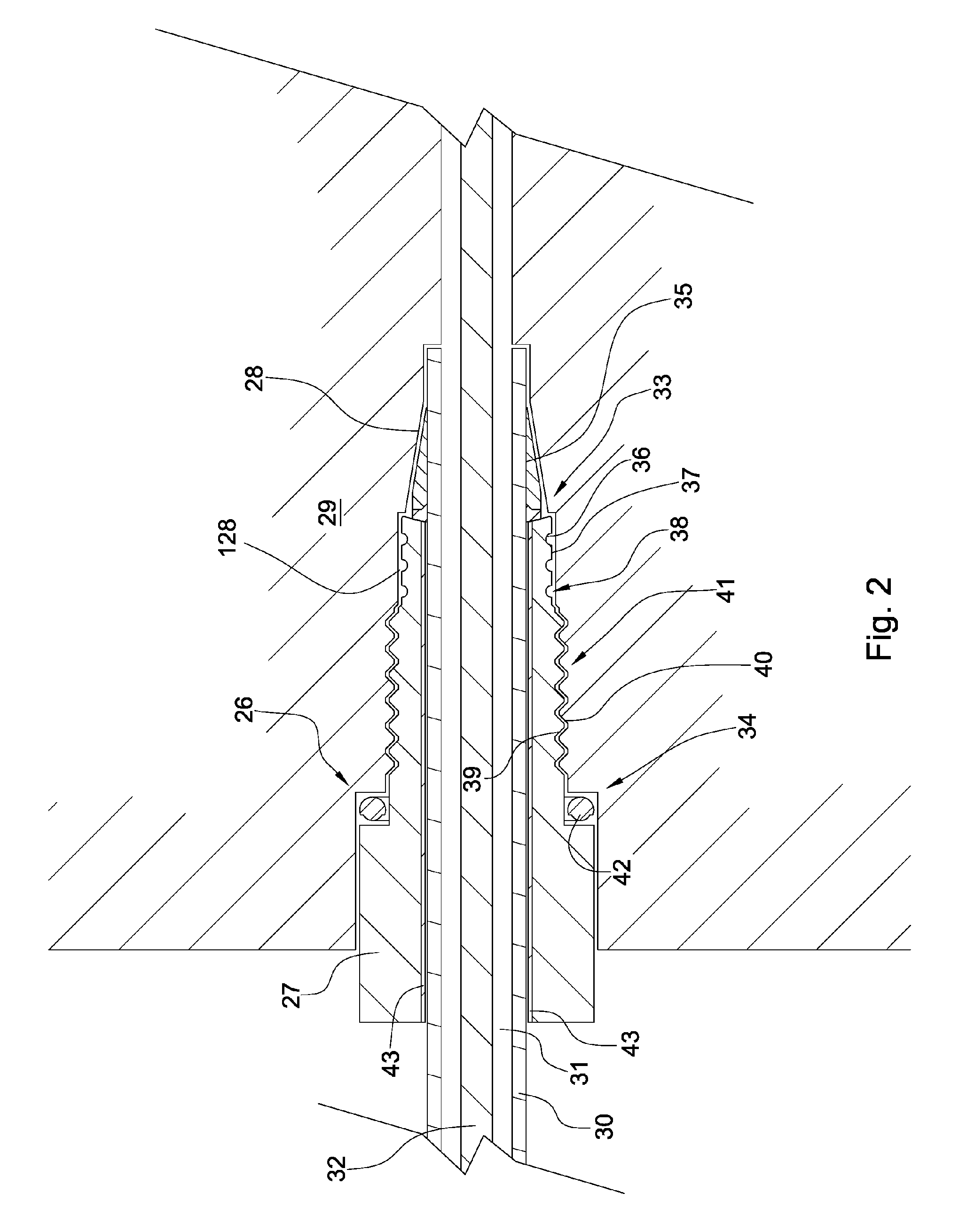
[0010] The present invention is a connection for use in pressure with a first and second surface stationary with respect to one another and a primary seal and secondary seal formed between the surfaces. Also a redundant labyrinth seal is formed between the first and second surfaces and intermediate the primary and secondary seals. The labyrinth seal may comprise grooves formed in the first or second surface. The first surface may be a retainer and the second surface may be a receptacle or a conduit. The labyrinth seal may allow for narrower connections, since traditional redundant seal components may be bulky.
[0011] In some embodiments of the invention the connection includes a retainer disposed within a housing receptacle and a conduit is disposed within a bore of the retainer. A primary seal is formed between the conduit and the receptacle and a secondary seal is formed between the retainer and the receptacle, or the secondary seal is formed between the conduit and the retainer. A labyrinth seal may be formed between the primary and secondary seal. The labyrinth seal may be formed between the conduit and the retainer or between the retainer and the housing receptacle. The labyrinth seal may have a plurality of bristles or segments. The labyrinth seal may be a fluid path comprising a plurality of sharp turns. Preferably, a cavity, which is formed by the surfaces, the primary seal and the secondary seal, is pressurized by a fluid. Pressurizing the cavity may help determine is a seal is properly assembled and may dissipate fluid velocity that may overcome the primary or secondary seals.

Problems solved by technology

Typically, the narrower the connection the easier it is to affix conduits or cables to or within the downhole tool, since the tool typically has limited space to accommodate connections.
The labyrinth seal may allow for narrower connections, since traditional redundant seal components may be bulky.

Method used


Image

  • High Pressure Connection
  • High Pressure Connection
  • High Pressure Connection

Examples


Embodiment Construction

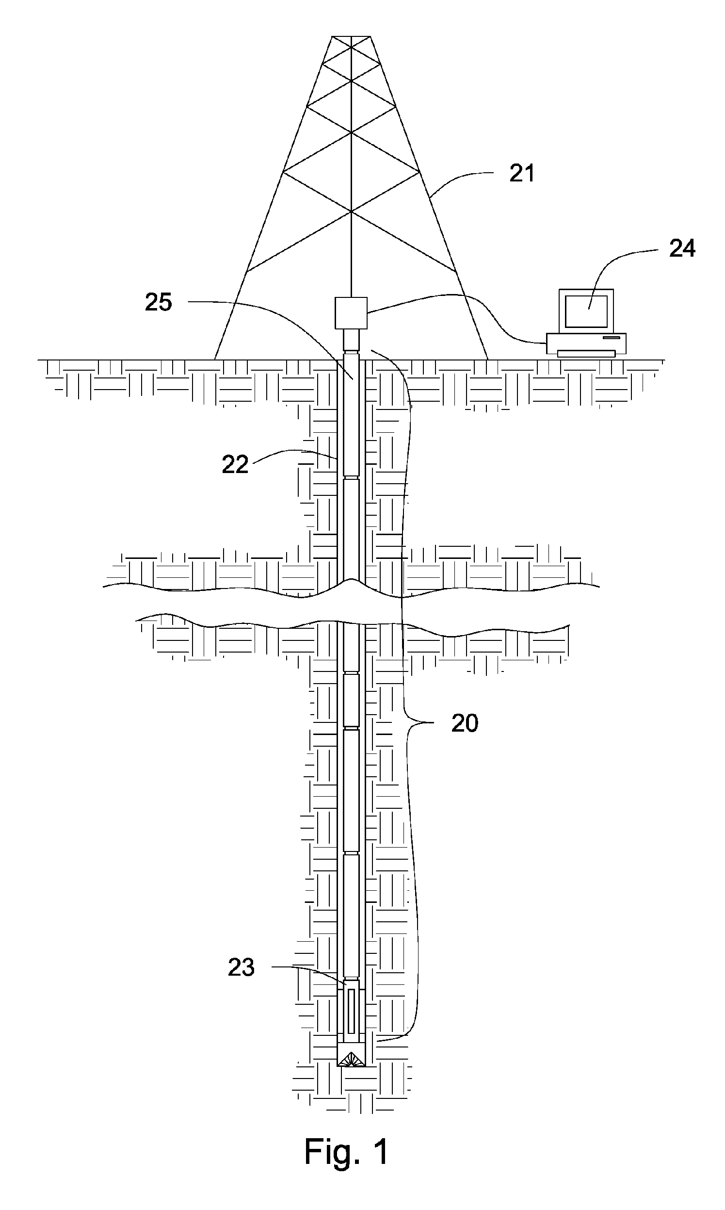
[0032]FIG. 1 shows a perspective view of a drill string 20 suspended within a drilling bore 22. A derrick 21 supports the drill string 20. Downhole tools 23, such as drilling hammers, drilling jars, sensors, drill bits, and other tools may be attached to the drill string 20. If a downhole transmission system is incorporated within the drill string 20, such as a downhole network, data may be transmitted to surface equipment 24 for real time analysis. Such systems may include those systems disclosed in U.S. Pat. No. 6,670,880 to Hall; U.S. Pat. No. 6,641,434 to Boyle; and U.S. Pat. No. 6,688,396 to Floerke; all of which are herein incorporated by reference for all that they disclose. Downhole tools 23 connected to an electrically conducting wireline (not shown) may also allow data to be transmitted to surface equipment 24 for analysis. The drill string 20 may comprises components 25 selected from the group consisting of coiled tubing, drill pipe, drill collars, heavyweight pipe, stabi...


PUM


Abstract

A connection for use in pressure includes a first and second surface stationary with respect to one another and a primary seal and secondary seal are formed between the surfaces and a labyrinth redundant seal is formed between the first and second surfaces and intermediate the primary and secondary seals. A connection for sealing against pressure may also include a retainer disposed within a housing receptacle a conduit disposed within a bore of the retainer. A primary seal may be formed between the conduit and the receptacle and a secondary seal may be formed between the retainer and the receptacle. A labyrinth seal may be formed between the retainer and the receptacle and intermediate the primary and secondary seals.

Description

BACKGROUND OF THE INVENTION [0001] The present invention relates to high pressure connections. More particularly the present invention relates to high pressure connections comprising redundant seals. Downhole pressure in drilling, production, and geothermal applications may reach 25,000 PSI and temperatures over 200 degrees Celsius. It may be desirable for wires and other forms of transmitting data in such applications to have robust connections to downhole tools. It may also be desirable for hydraulic or pneumatic systems to have connections capable of withstanding high pressures. Other factors such as thermal expansion, vibrations from actuating tools, and stresses on downhole tools help contribute to a need for a robust high pressure connection. [0002] U.S. Pat. No. 6,056,327 to Bouldin, et al. discloses a high pressure connector for engagement with a hydraulic conduit for use in high pressure conditions. A housing for receiving a conduit end is attachable to a primary retainer. ...

Claims


Application Information

Patent Timeline
Patent Type & Authority Applications(United States)
IPC IPC(8): F16L19/06
CPCE21B17/02E21B33/038F16L19/0218F16L19/06H01R13/5219H01R13/523
Inventor HALLFERNANDEZ, JOHN V.
Owner SCHLUMBERGER TECH CORP
Why Eureka
Eureka Blog
Learn More