Measure-initialized delay locked loop with live measurement

a delay lock and delay technology, applied in the field of synchronous circuits, can solve the problems of inability to synchronize the output clock with the external clock, take several clock cycles, and achieve the effect of wide frequency ranges

Inactive Publication Date: 2007-05-01
ROUND ROCK RES LLC
View PDF16 Cites 12 Cited by
  • Summary
  • Abstract
  • Description
  • Claims
  • Application Information

AI Technical Summary

Benefits of technology

[0013]The present disclosure allows a faster DLL reset in conditions where the external clock frequency has not changed, and the DLL has been previously locked, e.g. self-refresh exit. In cases where the system frequency is changing, e.g. clock frequency slewing, if the system is periodically updated with a new measurement, the DLL will be able to track much wider frequency ranges. Those, and other advantages and benefits, will be apparent from the description of the disclosure appearing hereinbelow.

Problems solved by technology

However, anytime the forward delay line is bypassed, the clock propagating to the outputs may not be synchronized to the external clock.
That may take several clock cycles.
As a result, the outputs cannot be synchronized anytime that a measurement is performed.

Method used


Image

  • Measure-initialized delay locked loop with live measurement
  • Measure-initialized delay locked loop with live measurement
  • Measure-initialized delay locked loop with live measurement

Examples


Embodiment Construction

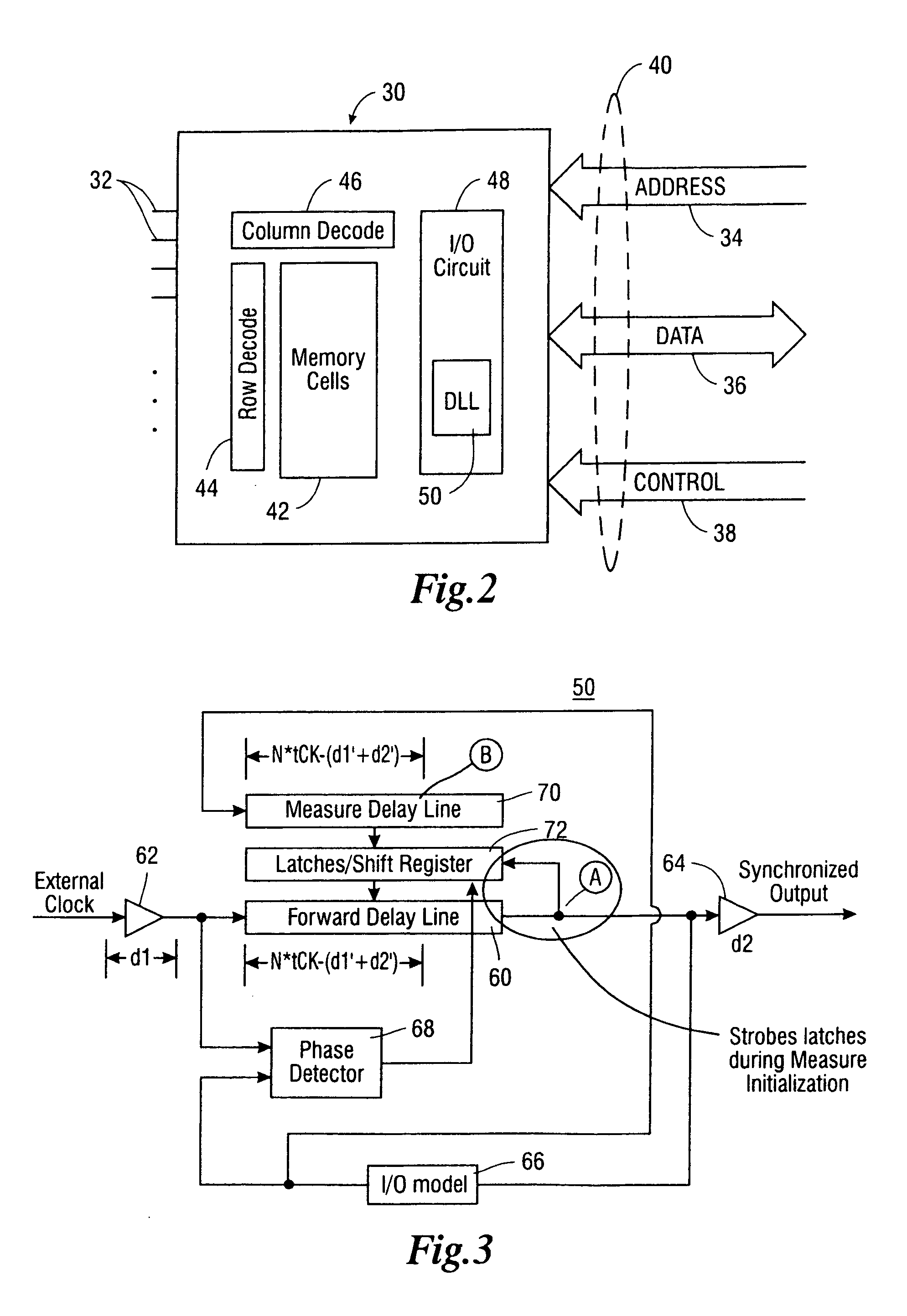
[0020]FIG. 2 is a simplified block diagram showing a memory chip or memory device 30. The memory chip 30 may be part of a DIMM (dual in-line memory module) or a PCB (printed circuit board) containing many such memory chips (not shown in FIG. 2). The memory chip 30 may include a plurality of pins 32 located outside of chip 30 for electrically connecting the chip 30 to other system devices. Some of those pins 32 may constitute memory address pins or address bus 34, data pins or data bus 36, and control pins or control bus 38. It is evident that each of the reference numerals 34, 36, 38 designates more than one pin in the corresponding bus. Further, it is understood that the schematic in FIG. 2 is for illustration only. That is, the pin arrangement or configuration in a typical memory chip may not be in the form shown in FIG. 2.

[0021]A processor or memory controller (not shown) may communicate with the chip 30 and perform memory read / write operations. The processor and the memory chip ...


PUM


Abstract

A method of operating a delay locked loop is comprised of producing a first output signal in response to a first lock point. A new lock point is measured, or otherwise determined, while continuing to produce the first output signal. Thereafter, a second output signal is produced in response to the new lock point. The new lock point data may be loaded into the delay locked loop while the delay locked loop continues to produce the first output signal. The delay locked loop switches from producing the first output signal, responsive to a first lock point, to producing the second output signal, responsive to the new lock point, in response to various conditions such as control signals, e.g. an auto refresh command, a precharge all command, a mode register load command, a power down entry, a power down exit (among others), in response to a timer, e.g., an internal timer (among others), or in response to environmental condition signals, e.g., a temperature sensor output signal (among others). Circuits and systems using the disclosed method are also disclosed. Because of the rules governing abstracts, this abstract should not be used to construe the claims.

Description

BACKGROUND[0001]1. Field of the Disclosure[0002]The present disclosure generally relates to synchronous circuits and, more particularly, to a method and apparatus for initializing a delay locked loop (DLL).[0003]2. Brief Description of Related Art[0004]Most digital logic implemented on integrated circuits is clocked synchronous sequential logic. In electronic devices such as synchronous dynamic random access memory circuits (SDRAMs), microprocessors, digital signal processors, etc., the processing, storage, and retrieval of information is coordinated or synchronized with a clock signal. The speed and stability of the clock signal determines to a large extent the data rate at which a circuit can function. Many high speed integrated circuit devices, such as SDRAMs, microprocessors, etc., rely upon clock signals to control the flow of commands, data, addresses, etc., into, through and out of the devices.[0005]In SDRAMs or other semiconductor memory devices, it is desirable to have the ...

Claims


Application Information

Patent Timeline
Patent Type & Authority Patents(United States)
IPC IPC(8): H03L7/06
CPCG11C7/1072G11C7/22G11C7/222H03L7/0814H03L7/0816H03L7/06
Inventor GOMM, TYLERBLODGETT, GREG
Owner ROUND ROCK RES LLC
Why Eureka
Try Eureka