Eureka AIR delivers breakthrough ideas for toughest innovation challenges, trusted by R&D personnel around the world.

Intake device for outboard motor

a technology for inlet devices and outboard motors, which is applied in the direction of combustion engines, combustion air/fuel air treatment, charge feed systems, etc. it can solve the problems of air intake into one cylinder that may interfere with air intake into another cylinder, space constraints are particularly limiting for an outboard motor intake system, and the relative short intake pipe is best. , to achieve the effect of minimizing intake interference and minimizing intake interferen

Active Publication Date: 2007-05-08
YAMAHA MARINE KK
View PDF7 Cites 5 Cited by
  • Summary
  • Abstract
  • Description
  • Claims
  • Application Information

AI Technical Summary

Benefits of technology

[0007]Accordingly, there is a need in the art for an outboard motor engine air intake system that can effectively increase intake pipe length to optimize engine air intake for low-to-medium and high engine speeds, that can minimize intake interference throughout the range of engine speeds, and that can fit effectively within the constrained space of an outboard motor cowling.
[0012]In a still further embodiment of the invention, an outboard motor is provided comprising an internal combustion engine and an air intake device generally enclosed within a cowling. The air intake device conducts air from within the cowling to a plurality of intake passages of the engine. The intake device comprises a plurality of main intake pipes, each main intake pipe comprising a downstream end communicating with a corresponding engine intake passage and comprising an upstream end. Each upstream end is connected to means for selectively forming a relatively long intake air path or forming a relatively short intake path. Means for minimizing intake interference at low / medium engine speeds and means for minimizing intake interference at high engine speeds are also provided.

Problems solved by technology

However, at high engine speeds, a relatively short intake pipe is best.
For example, in multi-cylinder engines, air intake into one cylinder may interfere with intake into another cylinder.
Also, space constraints are particularly limiting for an outboard motor intake system, as the internal combustion engine and associated components must be enclosed within a cowling.

Method used


Image

  • Intake device for outboard motor
  • Intake device for outboard motor
  • Intake device for outboard motor

Examples


Embodiment Construction

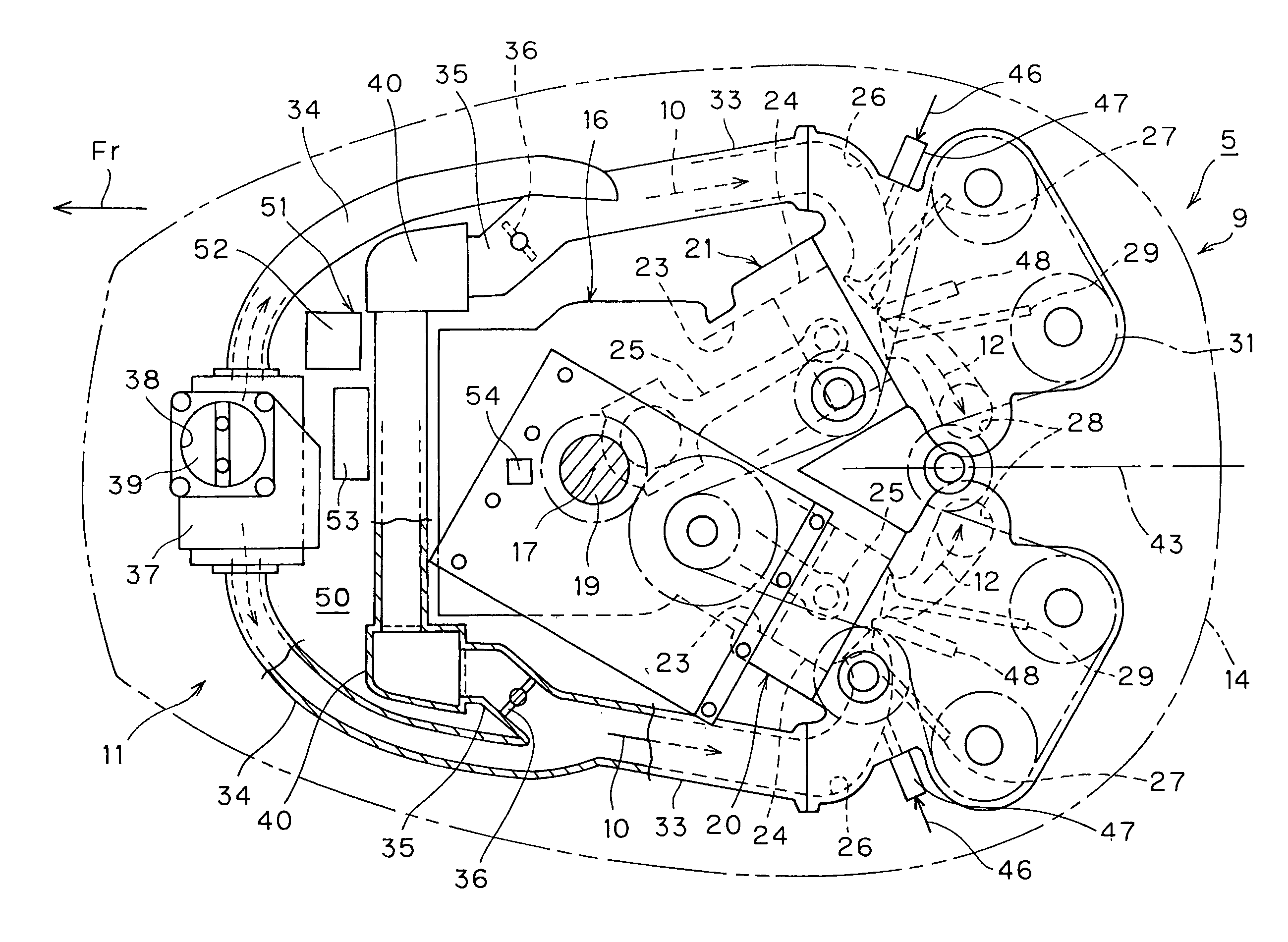
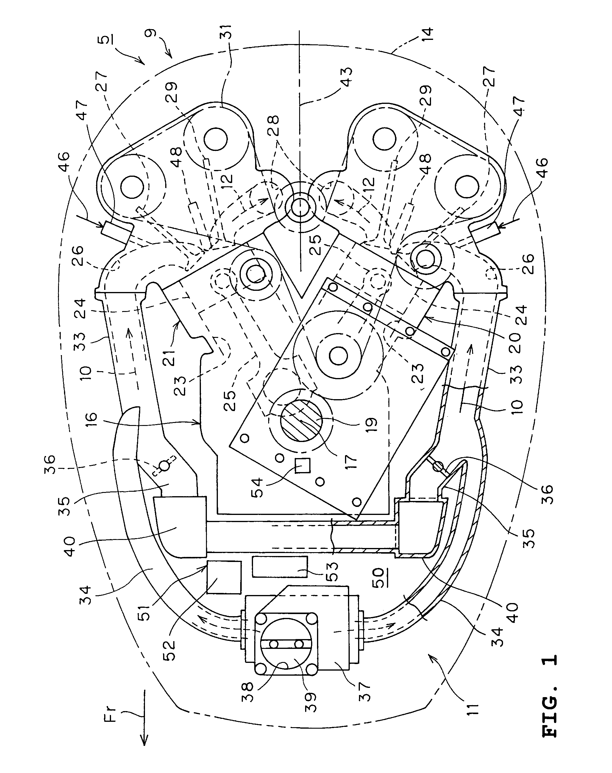
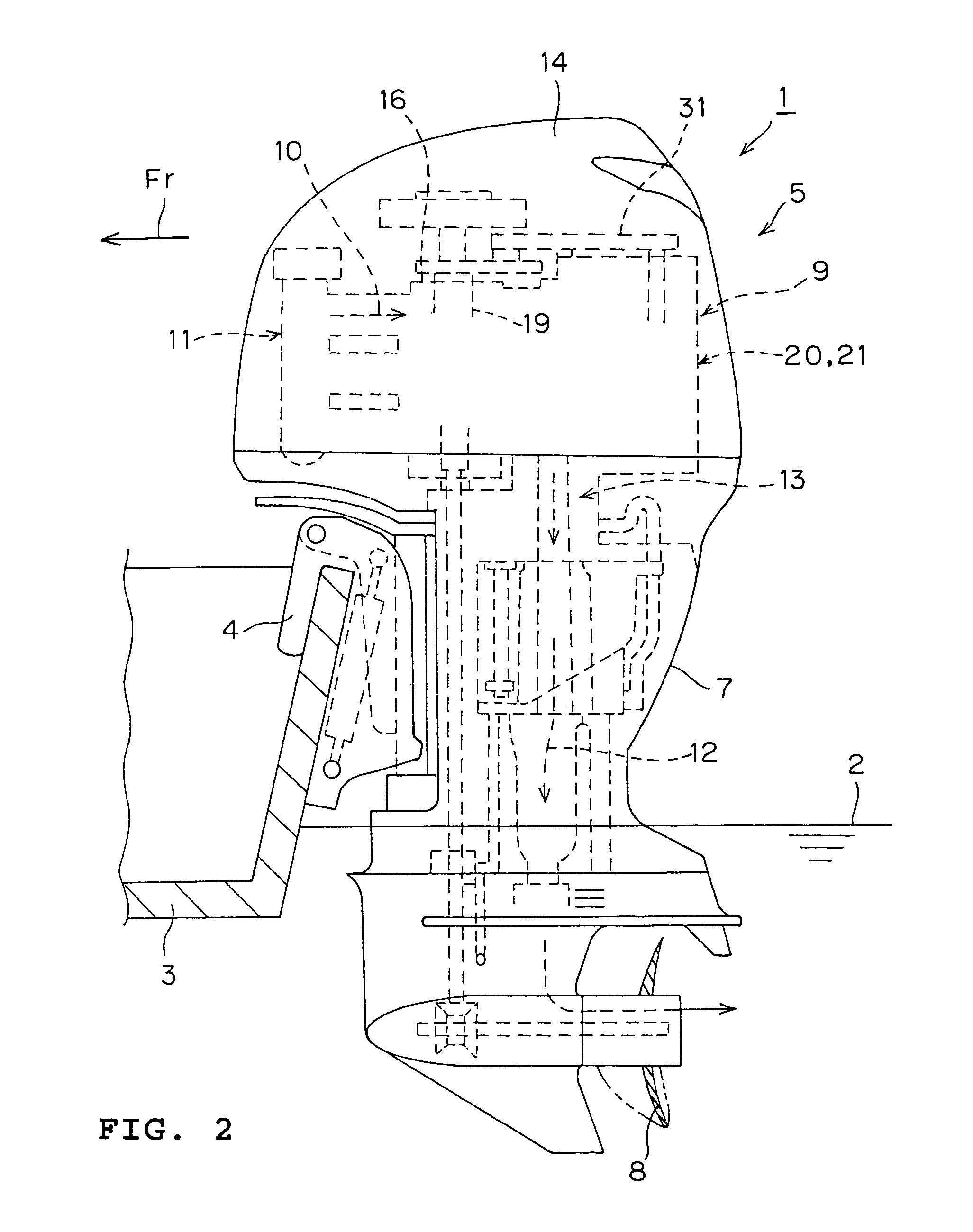
[0019]Preferred embodiments discussed herein describe aspects of an improved air intake device for a multi-cylinder internal combustion engine of an outboard motor. By employing aspects of the disclosed embodiments, the engine performance improves in all the speed ranges by obtaining a good inertia charge effect in all the speed ranges from a low / middle speed range to a high speed range of the engine.

[0020]Preferably, an intake device for a multi-cylinder internal combustion engine of an outboard motor, wherein the engine has a plurality of cylinders, includes a main intake pipe extending from each one of the cylinders, a first branch pipe extending from an extended, or upstream, end of each one of the main intake pipes, an extended end of each one of the first branch pipes communicating with the atmosphere, a second branch pipe extending from the extended, or upstream, end of said each one of the main intake pipes, and a switching valve for opening or closing an upstream end of eac...


PUM


Abstract

An engine air intake device for an outboard motor includes a plurality of main intake pipes corresponding to each cylinder. First and second branch pipes extend from an upstream end of each main part. The first branch pipes are longer than the second branch pipes. The second branch pipes each include a valve and are selectively closed. The first branch pipes open into a first surge tank. The second branch pipes open into a second surge tank that is formed separately from the first surge tank. In operation, the valves of the second branch pipes are open when the engine is operating in high engine speed and are closed at low-to-medium speeds.

Description

CROSS-REFERENCE TO RELATED APPLICATIONS[0001]This application claims priority to Japanese Patent Application No. JP 2004-335027, which was filed on Nov. 18, 2004, the entirety of which is hereby incorporated by reference.BACKGROUND OF THE INVENTION[0002]1. Field of the Invention[0003]The present invention relates to intake devices for outboard motors. More particularly, the present invention relates to an intake device that provides a good inertia charge effect in all speed ranges for an internal combustion engine of an outboard motor.[0004]2. Description of the Related Art[0005]Several factors affect the efficiency and effectiveness of delivering an air charge to an internal combustion engine. It has been found that at low-to-medium engine speeds, a relatively long intake pipe is desired to maximize engine performance. However, at high engine speeds, a relatively short intake pipe is best. It is known to provide an engine air intake system wherein the length of the intake pipes can...

Claims


Application Information

Patent Timeline
Patent Type & Authority Patents(United States)
IPC IPC(8): F02M35/10
CPCF02B27/02F02M35/10032F02M35/10045F02M35/10131F02M35/116F02M35/168F02B61/045Y02T10/146Y02T10/14F02B27/0221F02B27/0252F02B27/0273Y02T10/12
Inventor IWATA, YOSHIBUMITAKAHASHI, MASANORIMIYAZAKI, SATOSHI
Owner YAMAHA MARINE KK
Why Eureka
Eureka Blog
Learn More