Golf ball flight monitoring system

a monitoring system and golf ball technology, applied in the field of golf ball flight monitoring system, can solve the problems of unreliable accuracy, excessive swing evaluation time, and inability to accurately observe the many subtle features of golf swing

Inactive Publication Date: 2007-05-08
SWING DYNAMICS +1
View PDF38 Cites 86 Cited by
  • Summary
  • Abstract
  • Description
  • Claims
  • Application Information

AI Technical Summary

Benefits of technology

[0025]It is another object of the invention to provide a system and technique for monitoring and analyzing initial ball flight characteristics using a trigger for precisely timing the capture of temporally successive images.

Problems solved by technology

However, a golf swing is simply too fast in real time for clear human observation of its many subtle features.
This procedure can consume a great deal of swing evaluation time and its accuracy is unreliable.
Moreover, a calculation of such results of the backspin as loft during flight of the ball cannot be determined quickly as is desired during valuable swing evaluation time.
It is also difficult to distinguish the backspin from the sidespin imparted to the ball using the small single mark.
However, the one or more spots may again not be visible to the camera if they are rotated to the dark side of the ball when the image is captured on film.
In addition, any dirt or scuff mark on the ball may not be distinguishable from the spots in a practical apparatus being used for multiple swings in the field.
Also, the angular spacings of the sensors has to be very accurate or the calculated spin characteristics of the ball will be unreliable.
However, any one or all of the marks could again be rotated during a real golf swing to the dark side of the ball in which case the calculations would fail because the input data would be incomplete.

Method used


Image

  • Golf ball flight monitoring system
  • Golf ball flight monitoring system
  • Golf ball flight monitoring system

Examples


Embodiment Construction

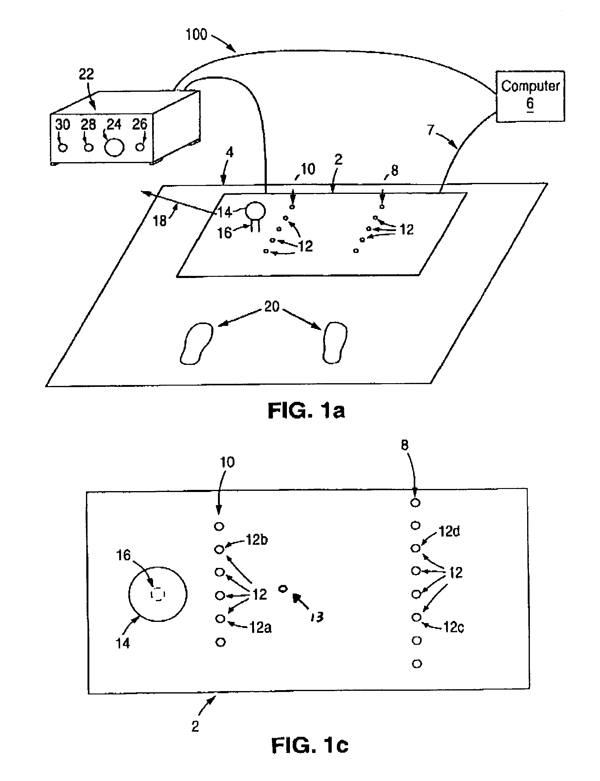
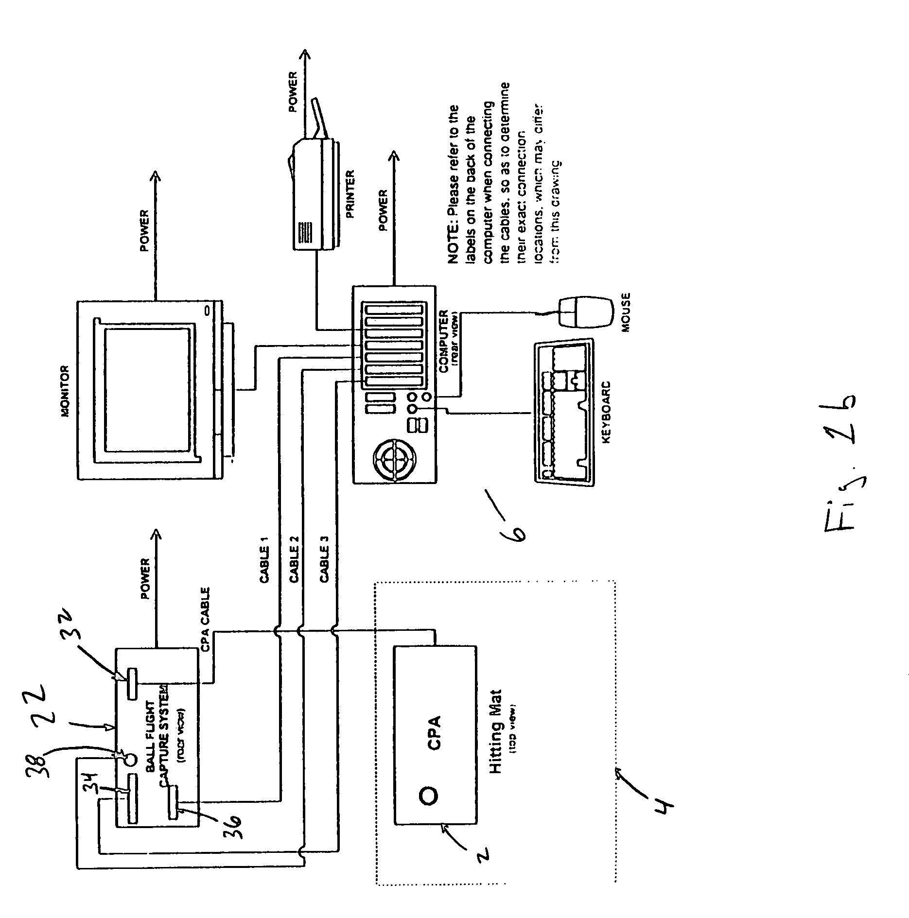
[0039]FIG. 1a schematically shows a perspective view of a ball flight monitoring system including an impact zone analyzer 2 arranged on a hitting mat 4. The impact zone analyzer 2 is imbedded within the hitting mat 4 such that the surface of the analyzer 2 is substantially coplanar with that of the hitting mat 4. The analyzer 2 is connected with a computer processor 6 such that data signals may be sent to the computer 6 from the analyzer 2. Although a direct connection 7 is shown between the analyzer 2 and the computer 6, the analyzer 2 may be indirectly connected to the computer 6 through ball flight capture device or system 22, described below.

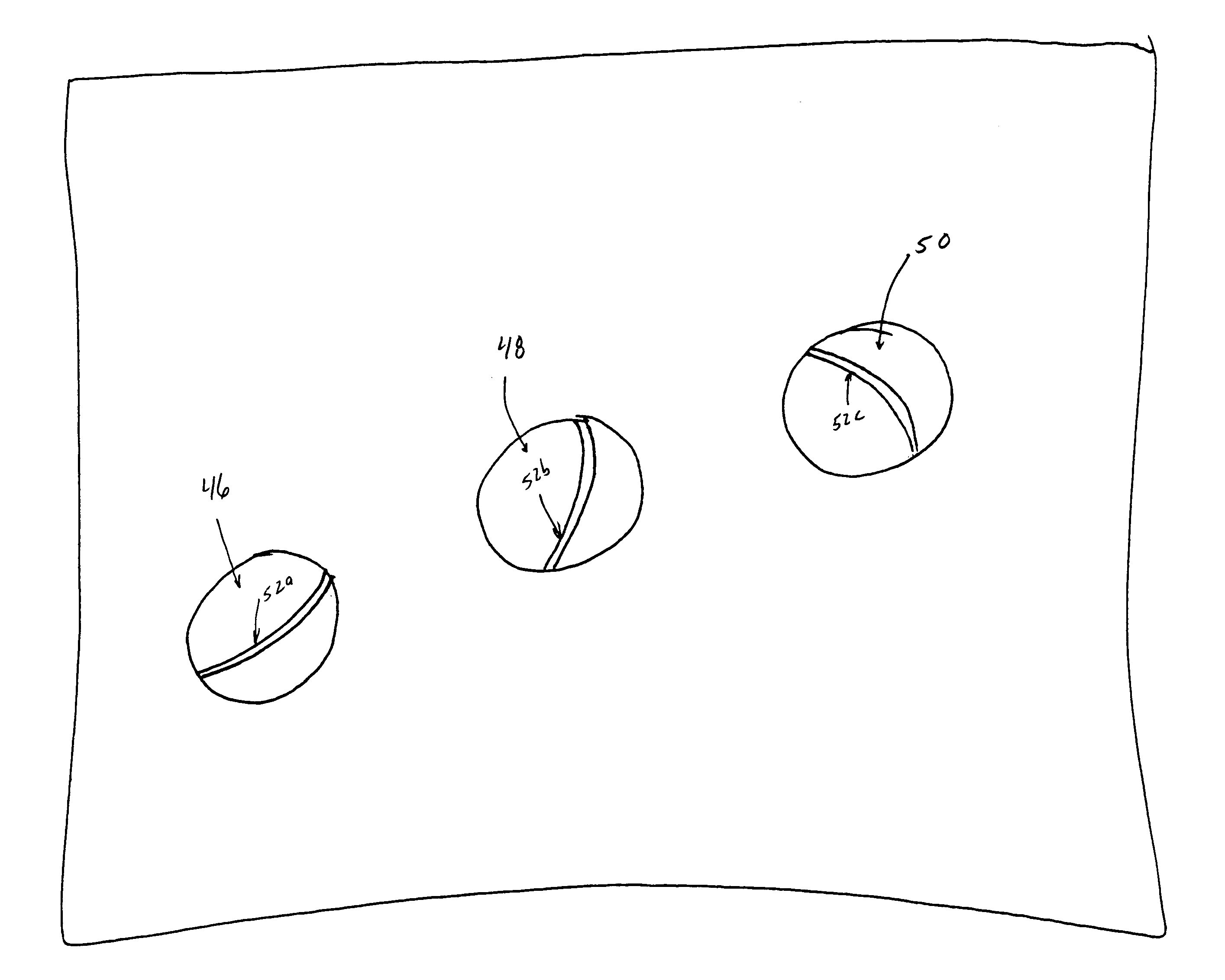
[0040]The analyzer has a first row 8 and a second row 10 of sensors 12 located behind a golf ball 14 on a tee 16. Preferably, each row 8, 10 has around twelve sensors 12. The sensors 12 are preferably photosensors such as light sensitive diodes or CCDs. The golf ball 14, of course, does not have to be located on the tee 16. The analyzer 2 is...


PUM


Abstract

A system is described for monitoring the swing path of a golf club head and for monitoring flight characteristics of a golf ball following impact. A processor utilizes data from spaced apart spaced sensor arrays in determining the club head speed and head angle of a golf club during the swing phase of the club. Image capture devices captures successive images of the ball after impact, and the system processor generates data reflecting ball flight characteristics based on a comparison of the images.

Description

PRIORITY[0001]This application claims the benefit of priority to U.S. Provisional Patent Application No. 60 / 117,824, filed Jan. 29, 1999.BACKGROUND OF THE INVENTION[0002]1. Field of the Invention[0003]The invention relates to a method and system for monitoring the flight of a golf ball after impact with a golf club head, and particularly to computer-controlled estimation of golf ball flight, impact timing and transfer efficiency characteristics.[0004]2. Discussion of the Related Art[0005]Golf swing and golf ball flight monitoring have been used as tools for golf instruction and for testing golf equipment such as golf clubs and golf balls for many years. Such details as club head angle and club speed at impact with the ball, as well as club take-away and downswing path, are known to be crucial in determining ultimately important ball flight characteristics, such as distance, direction, backspin and ball flight curvature after impact. However, a golf swing is simply too fast in real t...

Claims


Application Information

Patent Timeline
Patent Type & Authority Patents(United States)
IPC IPC(8): A63B69/36A63B57/00
CPCA63B24/0003A63B24/0021A63B69/3614A63B69/3658A63B71/06A63B43/008A63B2024/0028A63B2024/0031A63B2024/0034A63B2207/02A63B2220/05A63B2220/30A63B2220/35A63B2220/805A63B2220/807A63B2220/808A63B2220/89A63B2225/74
Inventor STIVERS, KEITHEPSTEIN, ALLANLAMB, STEVE R.
Owner SWING DYNAMICS
Why Eureka
Try Eureka