Injector with finger ring

a finger ring and injector technology, applied in the field of hand-operated devices, to achieve the effect of affecting the exact guidance and stable hold of the devi

Active Publication Date: 2007-05-15
ASICO +1
View PDF5 Cites 9 Cited by
  • Summary
  • Abstract
  • Description
  • Claims
  • Application Information

AI Technical Summary

Benefits of technology

[0005]It is an object of the invention to make available a device, of the type mentioned in the introductory part, with which the surgeon can determine the time and the extent of the rotational movement himself, without however adversely affecting the exact guidance and stable hold of the device.
[0008]In this way, it is possible for the surgeon to hold the injector and insert the lens safely into the eye with one hand. If at any time during the operation, particularly when the lens is inserted in the eye, he wishes to rotate the lens, this can be done by rotating the plunger or grip body, without the actuating means also rotating. The hand, or the thumb of this hand, does not have to change position. It is thus possible for the surgeon to rotate the device by hand, preferably with the other hand, without compromising the stable hold of the injector.

Problems solved by technology

However, this procedure requires that the surgeon has a very steady hand and has had a great deal of practice.

Method used


Image

  • Injector with finger ring
  • Injector with finger ring
  • Injector with finger ring

Examples


Embodiment Construction

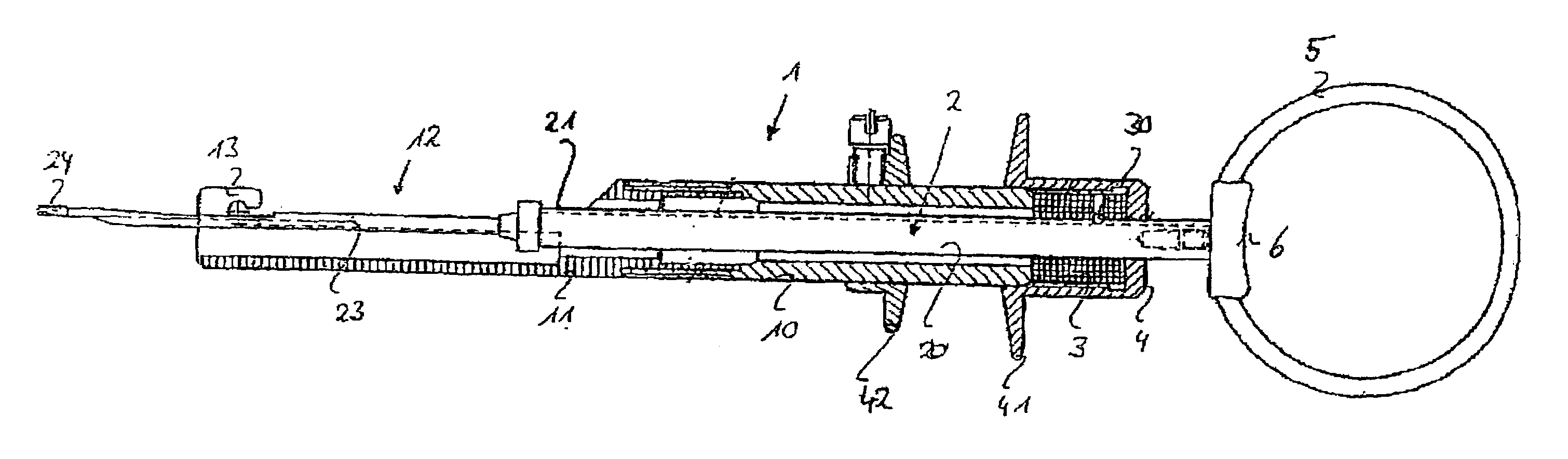
[0016]A hand-operated device according to the invention used for inserting a lens into an eye and referred to as an injector is shown in FIG. 1.

[0017]It is constructed in substantially the same way as the injector in aforementioned European patent application EP 01 810 823. The content of the latter, and that of the U.S. application Ser. No. 10 / 224,321 claiming this priority, are included here by reference.

[0018]The injector has an injector body or grip body 1 in which a plunger 2 is displaceably mounted. Both grip body 1 and plunger 2 are preferably made of metal, in particular titanium.

[0019]The grip body 1 has a sleeve 10 which merges at its front end into a grip front part 11. At its forward end directed away from the sleeve 10, the grip front part 11 has a lens holder 13, a suitable artificial lens being inserted via an insert window 12 which is arranged behind the lens holder 13.

[0020]The plunger 2 has a plunger rod 20 which merges into a plunger needle 23 with a plunger tip 2...


PUM


Abstract

A hand-operated injector for inserting a lens into an eye has a grip body (1) with a lens holder (13) for holding a lens, and a plunger (2) arranged displaceably in the grip body (1) for guided insertion of the lens into the eye. An actuating means (5, 6) for displacing the plunger (2) relative to the grip body (1) is arranged on the plunger (2), which actuating means (5, 6) is rotatable relative to the plunger (2). The injector can thus be rotated through any desired angle, without having to substantially change the position of the hand pressing on the plunger (2), in particular the position of the thumb.

Description

TECHNICAL FIELD[0001]The invention relates to a hand-operated device for inserting a lens into an eye,TECHNOLOGICAL BACKGROUND[0002]Nowadays, in ophthalmic surgery, replacing an opaque natural eye lens with an artificial lens is one of a number of routine procedures. However, this procedure requires that the surgeon has a very steady hand and has had a great deal of practice.[0003]For this reason, hand-operated devices referred to as injectors are known which permit a certain degree of guiding when fitting the artificial lens. These known injectors generally have a grip body, and a plunger which can be displaced in the grip body via a thread. In the front area of the grip body there is a lens holder into which an artificial lens to be inserted is placed. By rotating the plunger, this lens can then be pushed through a front opening of the lens holder, the lens being folded in the process, if appropriate. By further advancing the lens, it is introduced in the folded state into the eye...

Claims


Application Information

Patent Timeline
Patent Type & Authority Patents(United States)
IPC IPC(8): A61F9/00A61F2/16
CPCA61F2/1664
Inventor MEYER, ROLF
Owner ASICO
Why Eureka
Try Eureka