Pressing unit for a portioning machine

a portioning machine and pressing unit technology, applied in the field ofportioning machines, can solve the problems of high degree of control expenditure, additional limit to the achievable production speed, and corresponding requirements

Pending Publication Date: 2022-03-10
POLY CLIP SYST
View PDF6 Cites 2 Cited by
  • Summary
  • Abstract
  • Description
  • Claims
  • Application Information

AI Technical Summary

Benefits of technology

[0052]Further advantageously, provision may be made, in case the turret base is formed in two parts, for an essentially planar separating unit to be arranged between the base segment and the turret segment of the turret base. This makes it possible for a strand-like product inserted into the reception chute of the chute module of the magazine turret attachment to be positioned with precision.
[0053]The separating unit may be configured in various manners. However, it is advantageous if the essentially planar separating unit is an at least approximately circular metal sheet provided with at least one clearance arranged in the area of a chute portion of the turret base. A separating unit formed in this manner makes it possible to safely insert a strand-like product into a reception chute placed in a filling position and to transfer the strand-like product to a corresponding cutting device which is arranged in the area of a reception chute when the latter is located in the cutting position.

Problems solved by technology

However, the devices for pressure-compacting the strand-like product as proposed in these documents have a complicated structure and therefore require a corresponding, high degree of control expenditure.
A further drawback consists in the fact that when a portioning chamber is used, it must be emptied before it can be re-used, which sets an additional limit to the achievable production speed.

Method used


Image

  • Pressing unit for a portioning machine
  • Pressing unit for a portioning machine
  • Pressing unit for a portioning machine

Examples


Embodiment Construction

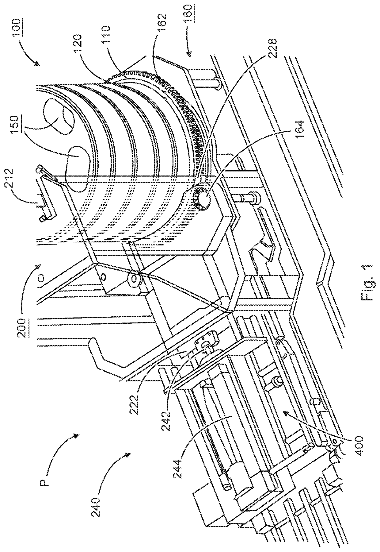
[0064]A portioning machine P according to the present invention and as shown in FIG. 1 includes a magazine turret attachment 100 for receiving a strand-like product, a pressing unit 200 for pressure-compacting the strand-like product, and a portioning and cutting device 300 for portioning and separating individual portions from the strand-like product (cf. FIG. 3), as well as a transporting apparatus 400 for removing the individual portions or groups of individual portions.

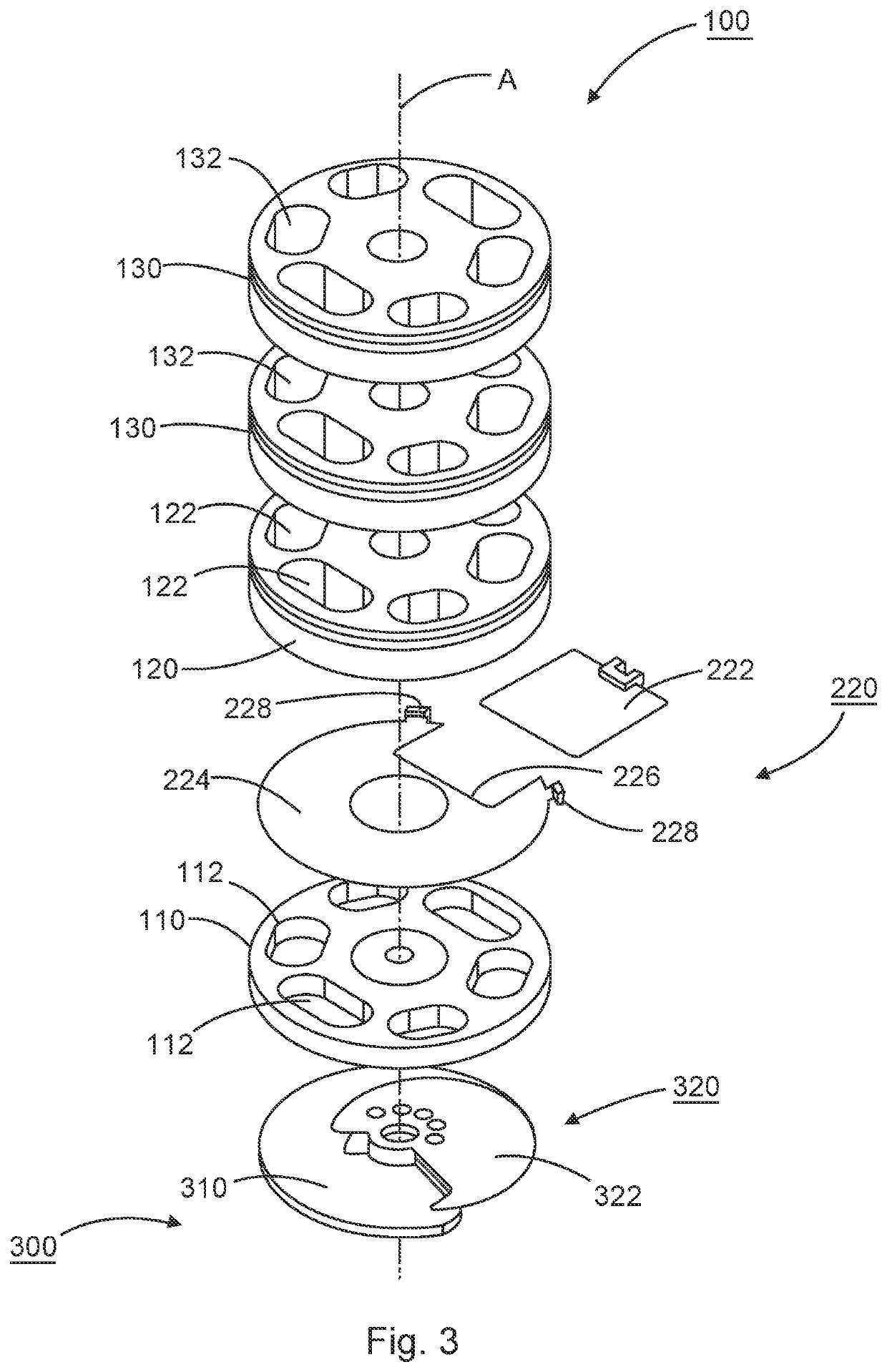
[0065]The magazine turret attachment 100 comprises a turret base having a central axis A, a disc-shaped base segment 110, and an equally disc-shaped turret segment 120 which are oriented coaxially with respect to each other.

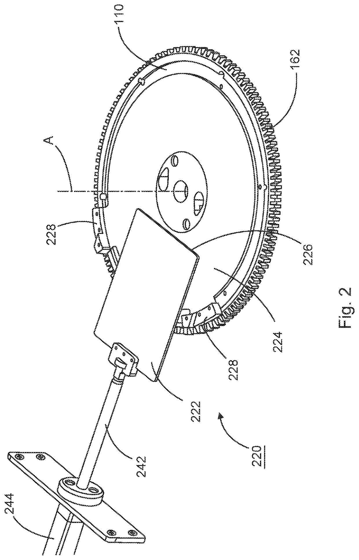
[0066]The base segment 110 has chute portions 112 which extend through the base segment 110 and are oriented parallel to the central axis A of the magazine turret attachment 100 (cf. FIGS. 2, 3). The chute portions 112 have an at least partially oval cross-section which is adapted to the strand...


PUM


Abstract

The present invention relates to a portioning machine for dividing a strand-like product into individual portions and a method of controlling such portioning machine. The portioning machine includes a magazine turret attachment for receiving the strand-like product, a pressing unit for pressure-compacting the strand-like product at least in its longitudinal direction, and a portioning and cutting device for portioning and separating individual portions from the strand-like product. The magazine turret attachment has a base segment and a turret segment which have chute portions oriented coaxially with respect to one another for forming at least one reception chute for the strand-like product and which are rotatable about a common axis for positioning the reception chute in a cutting position; and wherein the pressing unit for pressure-compacting the strand-like product has at least one pressure ram and a counter-pressure element. The counter-pressure element is a slide element arranged between the base segment and the turret segment of the magazine turret attachment and is reversibly movable in a direction at least approximately perpendicular to the axis of rotation of the magazine turret attachment between a release position and a closure position for unblocking or closing the reception chute placed in the cutting position.

Description

FIELD OF THE INVENTION[0001]The present invention relates to a portioning machine for dividing a strand-like product into individual portions.[0002]BACKGROUND[0003]Portioning machines are used, for example, to cut strand-like products such as meat products, in meat strands, as well as fish, poultry or sausage products, or bakery products into slices which are subsequently packaged as individual portions or packaged into portions containing several slices. In particular, when meat strands are cut into slices it is often desirable for the cut slices to be of equal thickness, equal weight and uniform shape. In order to achieve this, the meat strand that needs to be cut is pressed into the desired shape in order to achieve a homogeneous consistency along its length.[0004]European Patent Application 2 532 493 discloses a portioning machine which serves for cutting weight-accurate portions from a strand-like cutting material and which has a form tube turret containing several form tubes f...

Claims


Application Information

Patent Timeline
Patent Type & Authority Applications(United States)
IPC IPC(8): B26D1/147B26D1/29B26D7/06
CPCB26D1/147B26D1/29B26D2210/04B26D7/0683B26D7/0641A22C17/002B26D2210/02A22C11/00A22C7/0023
Inventor BERGMANN, MARTIN
Owner POLY CLIP SYST
Why Eureka
Try Eureka