
Portable hydraulic bushing press device and related method of manufacturing thereof

Inactive Publication Date: 2006-04-27
BROWN RAYMOND A
View PDF12 Cites 5 Cited by
  • Summary
  • Abstract
  • Description
  • Claims
  • Application Information

AI Technical Summary

Benefits of technology

[0006] Disclosed herein are embodiments of a portable hydraulic bushing press and related methods of pressing bushings in various components, such as automobile suspension components. The complete portable hydraulic bushing press system is configured to accomplish the installation of specific bushings in specific situations that cannot be done by conventional devices because existing equipment cannot perform the required tasks. The task is to quickly and safely insert bushings in suspension components of vehicles that demand extraordinary pressure due to close tolerances and a tight fit. This pressure is exerted on a specially reinforced “c-frame” utilizing specially designed cups that interface with the bushing and vehicle suspension component through integration with a hydraulic ram device and operator controlled foot pump connected to a source of pressurized air that allows for the bushing to be safely inserted in the fixture minimizing time and effort.

Problems solved by technology

The complete portable hydraulic bushing press system is configured to accomplish the installation of specific bushings in specific situations that cannot be done by conventional devices because existing equipment cannot perform the required tasks.

Method used


Image

  • Portable hydraulic bushing press device and related method of manufacturing thereof
  • Portable hydraulic bushing press device and related method of manufacturing thereof
  • Portable hydraulic bushing press device and related method of manufacturing thereof

Examples


Embodiment Construction

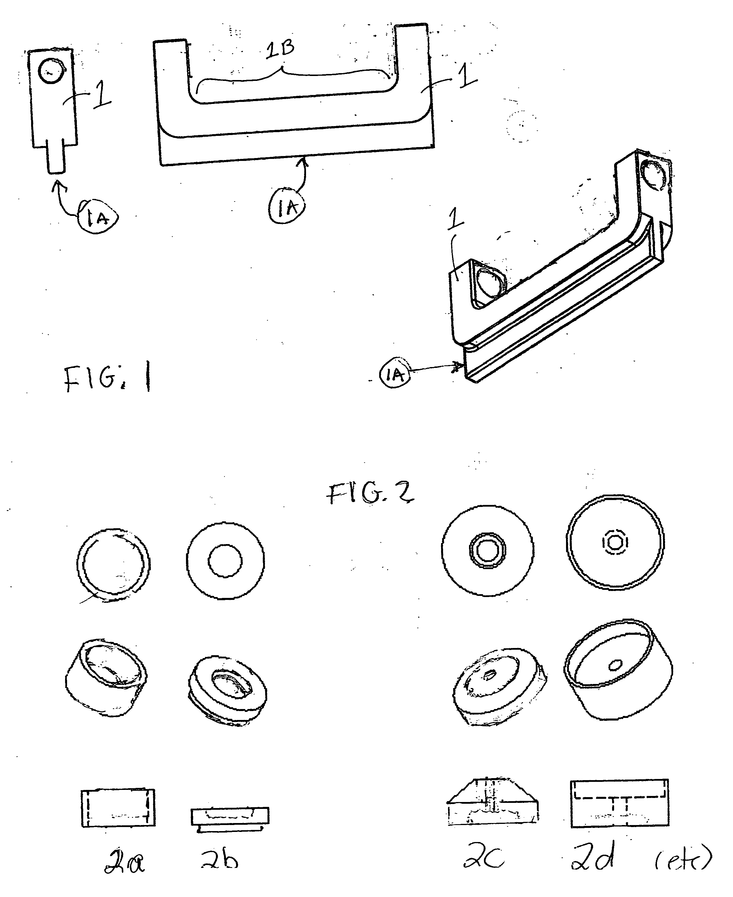
[0017] Looking initially at FIG. 1, a primary device (1) is illustrated as a c-frame that has been specially reinforced with an outside rib (1A) running the length of the frame 1 that not only increases the strength of the frame 1 but also minimizes weight. In addition, the rib 1A provides a flat and sturdy appendage, not found in conventional die-cast c-frames, which can be clamped or vised to a stable surface. This primary device 1 is coordinated with installation cups 2a, 2b, 2c, 2d, etc., which are illustrated in FIG. 2, that are specially designed to fit specific bushing 11 types and sizes.

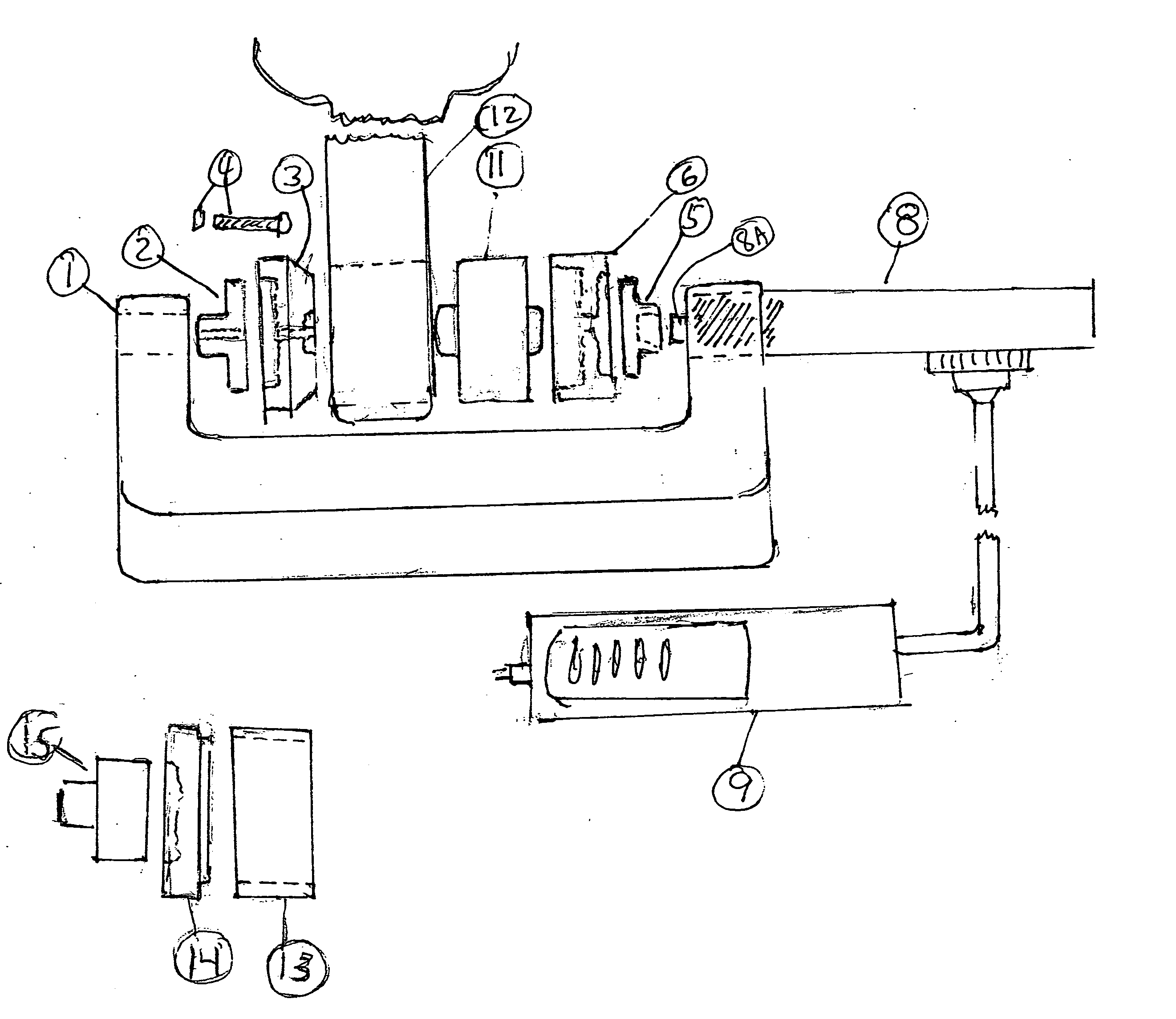
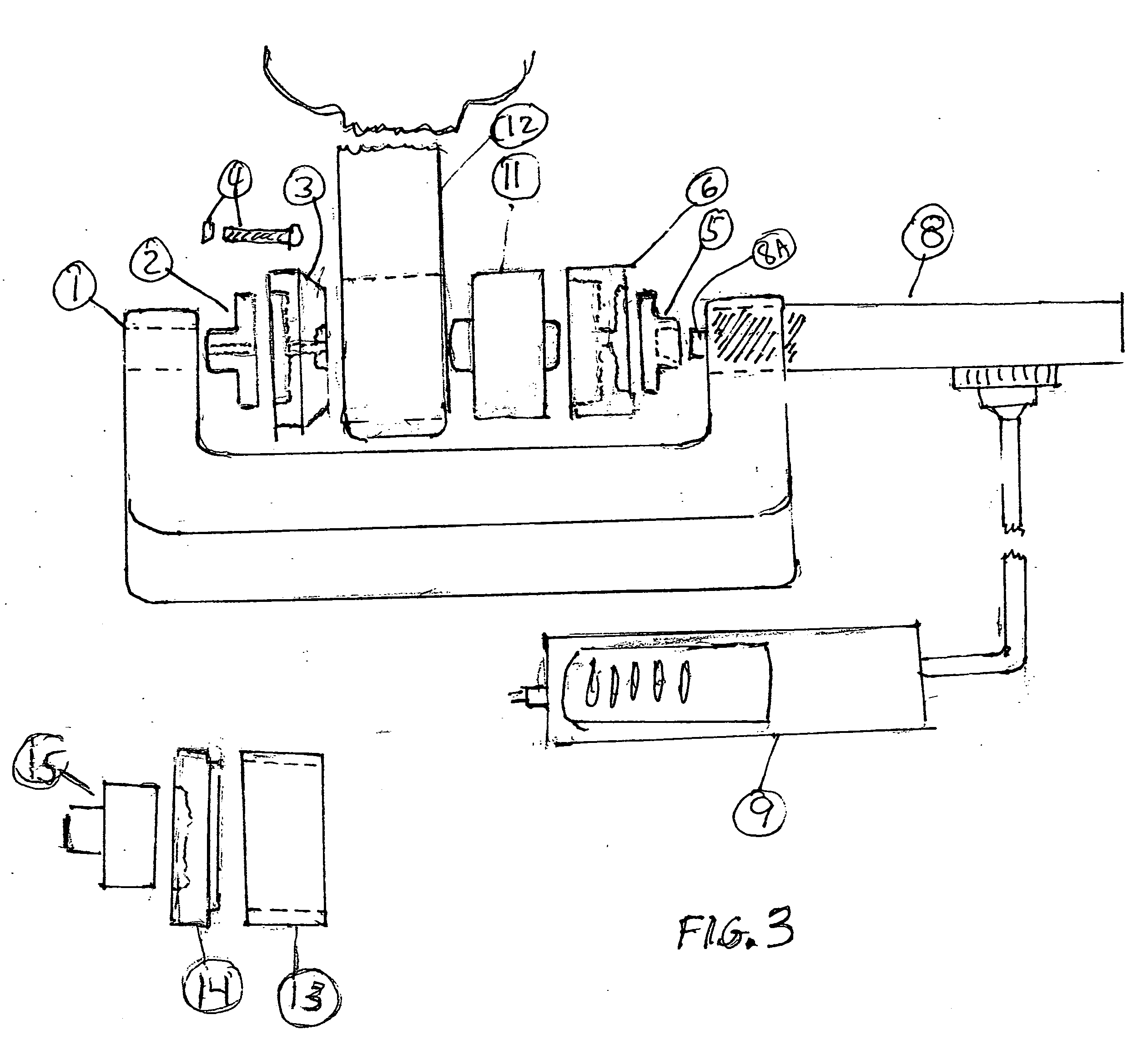
[0018] In FIG. 3, it is illustrated that the bushing 11 is placed within the arrangement of the primary device 1 and frame fixture 12 and cups 3, 6, and with the addition of the hydraulic assembly 8, having a hydraulic ram 8A extending therefrom during operation, connected to a hydraulic foot control pump 9. The pump 9 is illustrated in more detail in FIG. 4, and allows the bushing 12 to be ...


PUM

PropertyMeasurementUnit
Lengthaaaaaaaaaa

Abstract

Disclosed herein is a portable hydraulic press comprising a c-frame having a throat and first and second ends, the first and second ends locatable about a part to be pressed and a receiving structure. The press also includes a hydraulic assembly coupled to the c-frame and having a hydraulic ram configured to move through the first end and towards and away from an interior surface of the second end of the c-frame when the press is operated. It further includes a first installation cup coupled to the hydraulic ram, and having engaging surfaces designed to conform to exterior surfaces of an exterior surface of either the part or the receiving structure, and a second installation cup coupled to the interior surface of the second end of the c-frame and having engaging surfaces designed to conform to exterior surfaces of the other of the exterior surface of the part or the receiving structure. A hydraulic pump is coupled to the hydraulic assembly to operate the press.

Description

TECHNICAL FIELD [0001] Disclosed embodiments herein relate generally to hydraulic devices, and more particularly to a portable hydraulic bushing press and related method of pressing bushings in, for example, automobile suspension assemblies. BACKGROUND [0002] Since in the inception of the automobile as the preferred and most popular means of transportation, automobile manufacturers have continued to strive to improve various facets of the automobile, including ride quality. Key to improving ride quality is the suspension system of the automobile, which is engineered to absorb any of a number of bumps or other hazards found on and off today's roads. As such suspension systems move to absorb these hazards, so that the passengers do not absorb them, components within the suspension system continuously move and pivot, as per their design. For example, the frames (e.g., “A-frames”) in modern suspension systems are typically pivotally coupled to the automobile's chassis, and are configure...

Claims


Application Information

Patent Timeline
IPC IPC(8): B23P11/00
CPCB25B27/062Y10T29/4984Y10T29/49947B25B27/064
Inventor BROWN, RAYMOND A.
Owner BROWN RAYMOND A
Learn More